SiplaceX4_en.pdf - 第318页
1 - 2 S tudent Guide SIPLACE X Contents Edition 09/2005 2 7.4.6.2 Check the Zero calibration of the vacuum gen erator . . . . . . . . . . . . . . . . . . . . . 29 7.4.6.3 Calibrate closed vacuum . . . . . . . . . . . . .…

Student Guide SIPLACE X
Edition 09/2005 Contents
1
Chapter
Table of Contents
7 Twin-Head . . . . . . . . . . . . . . . . . . . . . . . . . . . . . . . . . . . . . . . . . . . . . . . . . . . . . . . . . 3
7.1 Overview . . . . . . . . . . . . . . . . . . . . . . . . . . . . . . . . . . . . . . . . . . . . . . . . . . . . . . . . . . . . . . . . . . . . . . . 3
7.1.1 Technical Data Twin- Head . . . . . . . . . . . . . . . . . . . . . . . . . . . . . . . . . . . . . . . . . . . . . 4
7.1.2 Parts on the Twin- Head . . . . . . . . . . . . . . . . . . . . . . . . . . . . . . . . . . . . . . . . . . . . . . . 5
7.1.2.1 Vacuum generator Twin- Head. . . . . . . . . . . . . . . . . . . . . . . . . . . . . . . . . . . . . . . 6
7.2 Reference Run Twin-head. . . . . . . . . . . . . . . . . . . . . . . . . . . . . . . . . . . . . . . . . . . . . . . . . . . . . . . . . 7
7.2.1 Reference run at Z axis . . . . . . . . . . . . . . . . . . . . . . . . . . . . . . . . . . . . . . . . . . . . . . . . 8
7.2.2 Reference run at D- axis . . . . . . . . . . . . . . . . . . . . . . . . . . . . . . . . . . . . . . . . . . . . . . . 9
7.2.3 Vacuum check. . . . . . . . . . . . . . . . . . . . . . . . . . . . . . . . . . . . . . . . . . . . . . . . . . . . . . . 9
7.2.4 Height reference run . . . . . . . . . . . . . . . . . . . . . . . . . . . . . . . . . . . . . . . . . . . . . . . . . 10
7.3 Pick up and Placement Cycle of the Twin Head . . . . . . . . . . . . . . . . . . . . . . . . . . . . . . . . . . . . . . 11
7.3.1 General . . . . . . . . . . . . . . . . . . . . . . . . . . . . . . . . . . . . . . . . . . . . . . . . . . . . . . . . . . . 11
7.3.2 Placement principle Twin-head . . . . . . . . . . . . . . . . . . . . . . . . . . . . . . . . . . . . . . . . . 12
7.3.3 Prepare pick up process module 1 . . . . . . . . . . . . . . . . . . . . . . . . . . . . . . . . . . . . . . 12
7.3.3.1 Pick up component module 1 . . . . . . . . . . . . . . . . . . . . . . . . . . . . . . . . . . . . . . . 13
7.3.4 Prepare pick up process module 2 . . . . . . . . . . . . . . . . . . . . . . . . . . . . . . . . . . . . . . 14
7.3.4.1 Pick up component module 2 . . . . . . . . . . . . . . . . . . . . . . . . . . . . . . . . . . . . . . . 14
7.3.5 Component centering module 1 and 2 . . . . . . . . . . . . . . . . . . . . . . . . . . . . . . . . . . . 15
7.3.6 Prepare placement 1st component . . . . . . . . . . . . . . . . . . . . . . . . . . . . . . . . . . . . . . 16
7.3.6.1 Place 1st component . . . . . . . . . . . . . . . . . . . . . . . . . . . . . . . . . . . . . . . . . . . . . 16
7.3.7 Prepare placement 2nd component . . . . . . . . . . . . . . . . . . . . . . . . . . . . . . . . . . . . . 17
7.3.7.1 Place 2nd component. . . . . . . . . . . . . . . . . . . . . . . . . . . . . . . . . . . . . . . . . . . . . 17
7.4 Adjustments . . . . . . . . . . . . . . . . . . . . . . . . . . . . . . . . . . . . . . . . . . . . . . . . . . . . . . . . . . . . . . . . . . . 19
7.4.1 Description of the boards on the Twin- Head . . . . . . . . . . . . . . . . . . . . . . . . . . . . . . 19
7.4.1.1 Head adapter Twin- Head . . . . . . . . . . . . . . . . . . . . . . . . . . . . . . . . . . . . . . . . . 19
7.4.1.2 Twin- Head main board . . . . . . . . . . . . . . . . . . . . . . . . . . . . . . . . . . . . . . . . . . . 20
7.4.1.3 Vision control board "IC camera" . . . . . . . . . . . . . . . . . . . . . . . . . . . . . . . . . . . . 21
7.4.2 Parameter and Calibrations. . . . . . . . . . . . . . . . . . . . . . . . . . . . . . . . . . . . . . . . . . . . 23
7.4.2.1 Overview calibration steps and parameter in the Sitest . . . . . . . . . . . . . . . . . . . 23
7.4.3 Parameter Twin- Head . . . . . . . . . . . . . . . . . . . . . . . . . . . . . . . . . . . . . . . . . . . . . . . 24
7.4.4 Calibrate D-Axis. . . . . . . . . . . . . . . . . . . . . . . . . . . . . . . . . . . . . . . . . . . . . . . . . . . . . 26
7.4.4.1 Manual Calculation of the ZPC D-axis . . . . . . . . . . . . . . . . . . . . . . . . . . . . . . . . 27
7.4.5 Calibrate head height . . . . . . . . . . . . . . . . . . . . . . . . . . . . . . . . . . . . . . . . . . . . . . . . 27
7.4.6 Zero calibration for pressure regulator on the Twin- Head . . . . . . . . . . . . . . . . . . . . 28
7.4.6.1 Zero calibration vacuum generator. . . . . . . . . . . . . . . . . . . . . . . . . . . . . . . . . . . 28

1 - 2
Student Guide SIPLACE X
Contents Edition 09/2005
2
7.4.6.2 Check the Zero calibration of the vacuum generator . . . . . . . . . . . . . . . . . . . . . 29
7.4.6.3 Calibrate closed vacuum . . . . . . . . . . . . . . . . . . . . . . . . . . . . . . . . . . . . . . . . . . 29
7.4.6.4 Check the pressure tightness of the vacuum system . . . . . . . . . . . . . . . . . . . . . 30
7.4.6.5 Check the "Air kiss" pressure . . . . . . . . . . . . . . . . . . . . . . . . . . . . . . . . . . . . . . . 31
7.4.7 Calibrating the Twin- Head . . . . . . . . . . . . . . . . . . . . . . . . . . . . . . . . . . . . . . . . . . . . 31
7.4.8 Mechanical adjustment the incremental encoder Z-axis . . . . . . . . . . . . . . . . . . . . . . 32
7.4.9 Vision DC/DC Converter . . . . . . . . . . . . . . . . . . . . . . . . . . . . . . . . . . . . . . . . . . . . . . 32
7.5 Nozzle changer. . . . . . . . . . . . . . . . . . . . . . . . . . . . . . . . . . . . . . . . . . . . . . . . . . . . . . . . . . . . . . . . . 33
7.5.1 Nozzle changer for Twin- head . . . . . . . . . . . . . . . . . . . . . . . . . . . . . . . . . . . . . . . . . 33
7.5.2 Position and assembly the nozzle changer . . . . . . . . . . . . . . . . . . . . . . . . . . . . . . . . 34
7.5.2.1 Position. . . . . . . . . . . . . . . . . . . . . . . . . . . . . . . . . . . . . . . . . . . . . . . . . . . . . . . . 34
7.5.2.2 Assembly nozzle changer magazine . . . . . . . . . . . . . . . . . . . . . . . . . . . . . . . . . 35
7.5.2.3 Description of the functions . . . . . . . . . . . . . . . . . . . . . . . . . . . . . . . . . . . . . . . . 36
7.6 Axis control . . . . . . . . . . . . . . . . . . . . . . . . . . . . . . . . . . . . . . . . . . . . . . . . . . . . . . . . . . . . . . . . . . . 37
7.6.1 Overview Axis control Z- and D-Axis . . . . . . . . . . . . . . . . . . . . . . . . . . . . . . . . . . . . 37
7.6.1.1 Overview positioning time for the Twin- head. . . . . . . . . . . . . . . . . . . . . . . . . . . 38
7.6.2 Track signals head axes . . . . . . . . . . . . . . . . . . . . . . . . . . . . . . . . . . . . . . . . . . . . . . 39
7.6.2.1 Test set up . . . . . . . . . . . . . . . . . . . . . . . . . . . . . . . . . . . . . . . . . . . . . . . . . . . . . 39
7.6.3 Axis control Twin- Head Z-axis . . . . . . . . . . . . . . . . . . . . . . . . . . . . . . . . . . . . . . . . . 41
7.6.3.1 Check the dynamic of Z-axis . . . . . . . . . . . . . . . . . . . . . . . . . . . . . . . . . . . . . . . 41
7.6.3.2 Test setup with Axis testbox . . . . . . . . . . . . . . . . . . . . . . . . . . . . . . . . . . . . . . . . 42
7.6.3.3 Test setup with SAT-Box . . . . . . . . . . . . . . . . . . . . . . . . . . . . . . . . . . . . . . . . . . 43
7.6.3.4 Check the function of the force sensor . . . . . . . . . . . . . . . . . . . . . . . . . . . . . . . . 45
7.6.4 Axis control Twin- Head D-axis . . . . . . . . . . . . . . . . . . . . . . . . . . . . . . . . . . . . . . . . . 47
7.6.4.1 Check the dynamic of D-Axis . . . . . . . . . . . . . . . . . . . . . . . . . . . . . . . . . . . . . . . 47
7.6.4.2 Test setup. . . . . . . . . . . . . . . . . . . . . . . . . . . . . . . . . . . . . . . . . . . . . . . . . . . . . . 48
1 - 3
Student Guide SIPLACE X
Edition 09/2005 7 Twin-Head
3
7 Twin-Head
7.1 Overview
The TWIN-head consists of two P&P heads of same model coupled together, who work according
to the Pick&Place principle. The second P&P head is rotated 180 degrees. For the TWIN-head,
new nozzles (Type 5xx) were developed. However, the nozzles of the Pick&Place head type 4xx
and the nozzles of the Collect&Place heads type 8xx and 9xx we can use with an adapter.
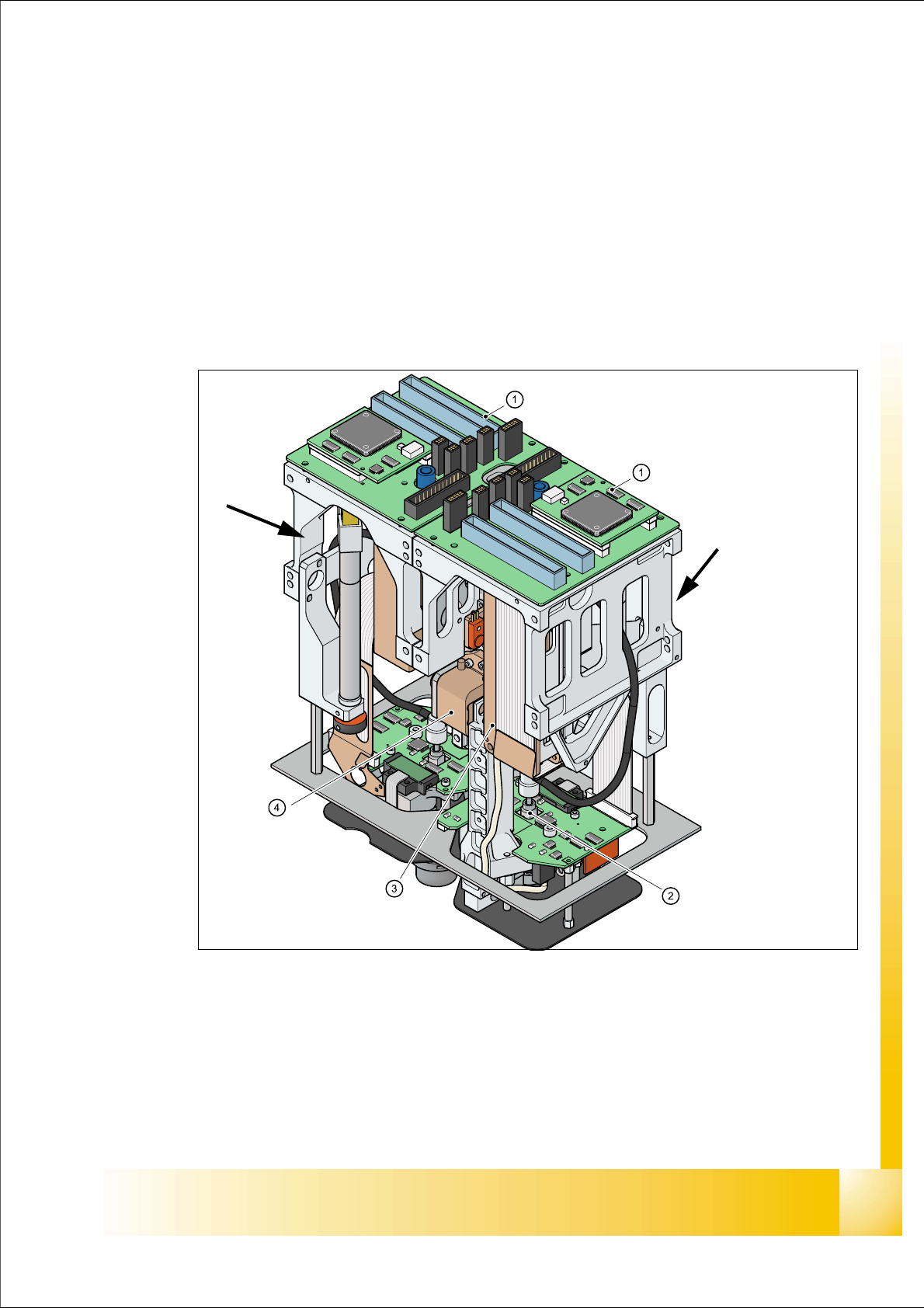
Fig. 7.1 - 1 TWIN- head
1. Main board on modul 1 and modul 2
2. D-Axis
3. Linear motorZ-Axis
4. Incremental measurement system Z-Axis
Modul 1
Modul 2, rotate 180 °
concerning Modul 1.