SiplaceX4_en.pdf - 第319页
1 - 3 S tudent Guide SIPLACE X Edition 09/2005 7 T win-Head 3 7 T win-Head 7.1 Overview The TWIN-head consist s of two P&P heads of sa me model cou pled togeth er , who wor k according to the Pick&Place principle…

1 - 2
Student Guide SIPLACE X
Contents Edition 09/2005
2
7.4.6.2 Check the Zero calibration of the vacuum generator . . . . . . . . . . . . . . . . . . . . . 29
7.4.6.3 Calibrate closed vacuum . . . . . . . . . . . . . . . . . . . . . . . . . . . . . . . . . . . . . . . . . . 29
7.4.6.4 Check the pressure tightness of the vacuum system . . . . . . . . . . . . . . . . . . . . . 30
7.4.6.5 Check the "Air kiss" pressure . . . . . . . . . . . . . . . . . . . . . . . . . . . . . . . . . . . . . . . 31
7.4.7 Calibrating the Twin- Head . . . . . . . . . . . . . . . . . . . . . . . . . . . . . . . . . . . . . . . . . . . . 31
7.4.8 Mechanical adjustment the incremental encoder Z-axis . . . . . . . . . . . . . . . . . . . . . . 32
7.4.9 Vision DC/DC Converter . . . . . . . . . . . . . . . . . . . . . . . . . . . . . . . . . . . . . . . . . . . . . . 32
7.5 Nozzle changer. . . . . . . . . . . . . . . . . . . . . . . . . . . . . . . . . . . . . . . . . . . . . . . . . . . . . . . . . . . . . . . . . 33
7.5.1 Nozzle changer for Twin- head . . . . . . . . . . . . . . . . . . . . . . . . . . . . . . . . . . . . . . . . . 33
7.5.2 Position and assembly the nozzle changer . . . . . . . . . . . . . . . . . . . . . . . . . . . . . . . . 34
7.5.2.1 Position. . . . . . . . . . . . . . . . . . . . . . . . . . . . . . . . . . . . . . . . . . . . . . . . . . . . . . . . 34
7.5.2.2 Assembly nozzle changer magazine . . . . . . . . . . . . . . . . . . . . . . . . . . . . . . . . . 35
7.5.2.3 Description of the functions . . . . . . . . . . . . . . . . . . . . . . . . . . . . . . . . . . . . . . . . 36
7.6 Axis control . . . . . . . . . . . . . . . . . . . . . . . . . . . . . . . . . . . . . . . . . . . . . . . . . . . . . . . . . . . . . . . . . . . 37
7.6.1 Overview Axis control Z- and D-Axis . . . . . . . . . . . . . . . . . . . . . . . . . . . . . . . . . . . . 37
7.6.1.1 Overview positioning time for the Twin- head. . . . . . . . . . . . . . . . . . . . . . . . . . . 38
7.6.2 Track signals head axes . . . . . . . . . . . . . . . . . . . . . . . . . . . . . . . . . . . . . . . . . . . . . . 39
7.6.2.1 Test set up . . . . . . . . . . . . . . . . . . . . . . . . . . . . . . . . . . . . . . . . . . . . . . . . . . . . . 39
7.6.3 Axis control Twin- Head Z-axis . . . . . . . . . . . . . . . . . . . . . . . . . . . . . . . . . . . . . . . . . 41
7.6.3.1 Check the dynamic of Z-axis . . . . . . . . . . . . . . . . . . . . . . . . . . . . . . . . . . . . . . . 41
7.6.3.2 Test setup with Axis testbox . . . . . . . . . . . . . . . . . . . . . . . . . . . . . . . . . . . . . . . . 42
7.6.3.3 Test setup with SAT-Box . . . . . . . . . . . . . . . . . . . . . . . . . . . . . . . . . . . . . . . . . . 43
7.6.3.4 Check the function of the force sensor . . . . . . . . . . . . . . . . . . . . . . . . . . . . . . . . 45
7.6.4 Axis control Twin- Head D-axis . . . . . . . . . . . . . . . . . . . . . . . . . . . . . . . . . . . . . . . . . 47
7.6.4.1 Check the dynamic of D-Axis . . . . . . . . . . . . . . . . . . . . . . . . . . . . . . . . . . . . . . . 47
7.6.4.2 Test setup. . . . . . . . . . . . . . . . . . . . . . . . . . . . . . . . . . . . . . . . . . . . . . . . . . . . . . 48
1 - 3
Student Guide SIPLACE X
Edition 09/2005 7 Twin-Head
3
7 Twin-Head
7.1 Overview
The TWIN-head consists of two P&P heads of same model coupled together, who work according
to the Pick&Place principle. The second P&P head is rotated 180 degrees. For the TWIN-head,
new nozzles (Type 5xx) were developed. However, the nozzles of the Pick&Place head type 4xx
and the nozzles of the Collect&Place heads type 8xx and 9xx we can use with an adapter.
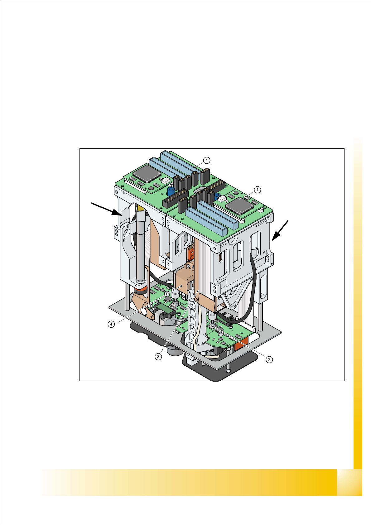
Fig. 7.1 - 1 TWIN- head
1. Main board on modul 1 and modul 2
2. D-Axis
3. Linear motorZ-Axis
4. Incremental measurement system Z-Axis
Modul 1
Modul 2, rotate 180 °
concerning Modul 1.

1 - 4
Student Guide SIPLACE X
7 Twin-Head Edition 09/2005
4
7.1.1 Technical Data Twin- Head
Fig. 7.1 - 2 Technical data TWIN- head
Placement accuracy (X/Y) 35µm by 4sigma with IC-camera
Placement accuracy (X/Y) 30µm by 4sigma with FC-camera
Placement accuracy (Angle) 0,07° by 4sigma
Placement speed 3500 cph
Maximum component size: 50 up to 40 mm single measurement on both segments
69 up to 10 mm multiple measurement by both segments
125 up to 10mm multiple measurement by one segment
200 up to 125mm multiple measurement with restriction
Max. component height 25 mm
Placement force 1-15 N
D-Axis / Resolution direct drive / 0,001 degree
Z-Axis / Resolution Linear motor / 0,5 µm
Travel range Z-axis app. 60 mm
Nozzle types 5xx (4xx, 8xx, 9xx with adapter)
Distance between the segments approx. 71,00 mm
Max. weight of component 100g
Option High Force Twin Head
Placement Force max. 30 N