SiplaceX4_en.pdf - 第324页
1 - 8 S tudent Guide SIPLACE X 7 T win-Head Edition 09/2005 8 7.2.1 Reference run at Z axis Fig. 7.2 - 2 Reference run Z-axis 1. Incremental scale mounted on mo veable pa rt of the Z-Axis 2. Fixed Increm ental encod er 3…
1 - 7
Student Guide SIPLACE X
Edition 09/2005 7 Twin-Head
7
7.2 Reference Run Twin-head
The TWIN-head consist of two segments which have 2 axes Z and D and the X and Y axes at the
Gantry.
Before you start the reference run the retract cylinder move out to the lower home position. On
both modules the vacuum is on, until the vacuum generator is initialized.
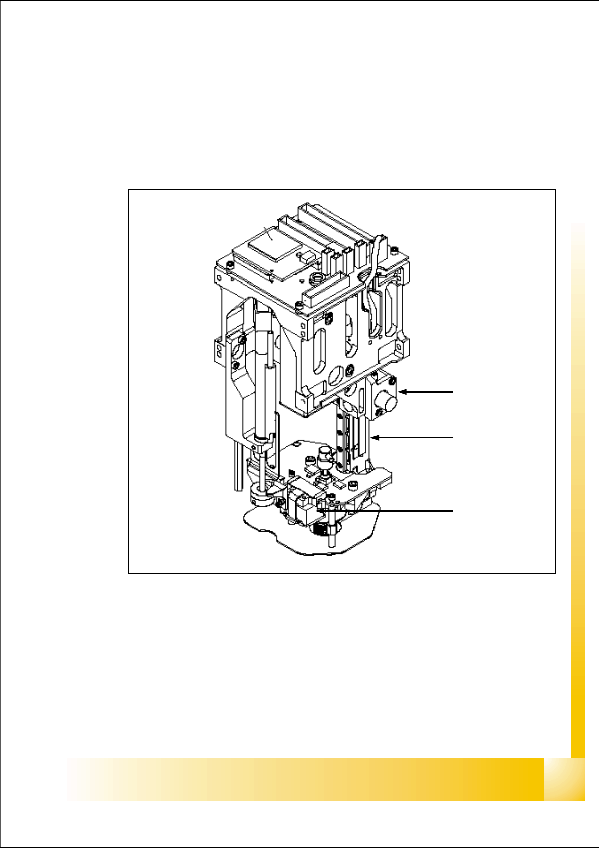
Fig. 7.2 - 1 TWIN-head Z,D- axes
1. Z-axis incremental encoder
2. Z-axis linear incremental scale
3. D-axis incremental encoder with incremental glass scale
1
3
2
1 - 8
Student Guide SIPLACE X
7 Twin-Head Edition 09/2005
8
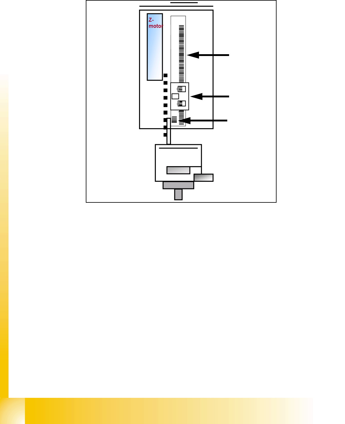
7.2.1 Reference run at Z axis
Fig. 7.2 - 2 Reference run Z-axis
1. Incremental scale mounted on moveable part of the Z-Axis
2. Fixed Incremental encoder
3. Zero puls on the incrementale scale (only one for Z-axis)
– Z-Axis search for the commutation point of the linear motors (in a special mode because of the
danger of a movement downwards). (A 3 phase motor move on and on when the current is
switched from 1 phase to the next one, at the correct time and in the correct sequence).
– First one of the phases is connect to the power supply. With the incremental encoder the
movement is measured.
– Than the current is switched to the next phase and this movement is measured too. The ma-
chine repeat this to check the measurement values.
– Then the Z-Axis move upwards to the Zero pulse and load the zero point correction.
– The zero point correction , max.- and min. travel range of the Z axis will determined if you
calibrate the head height.
1
2
3
1 - 9
Student Guide SIPLACE X
Edition 09/2005 7 Twin-Head
9
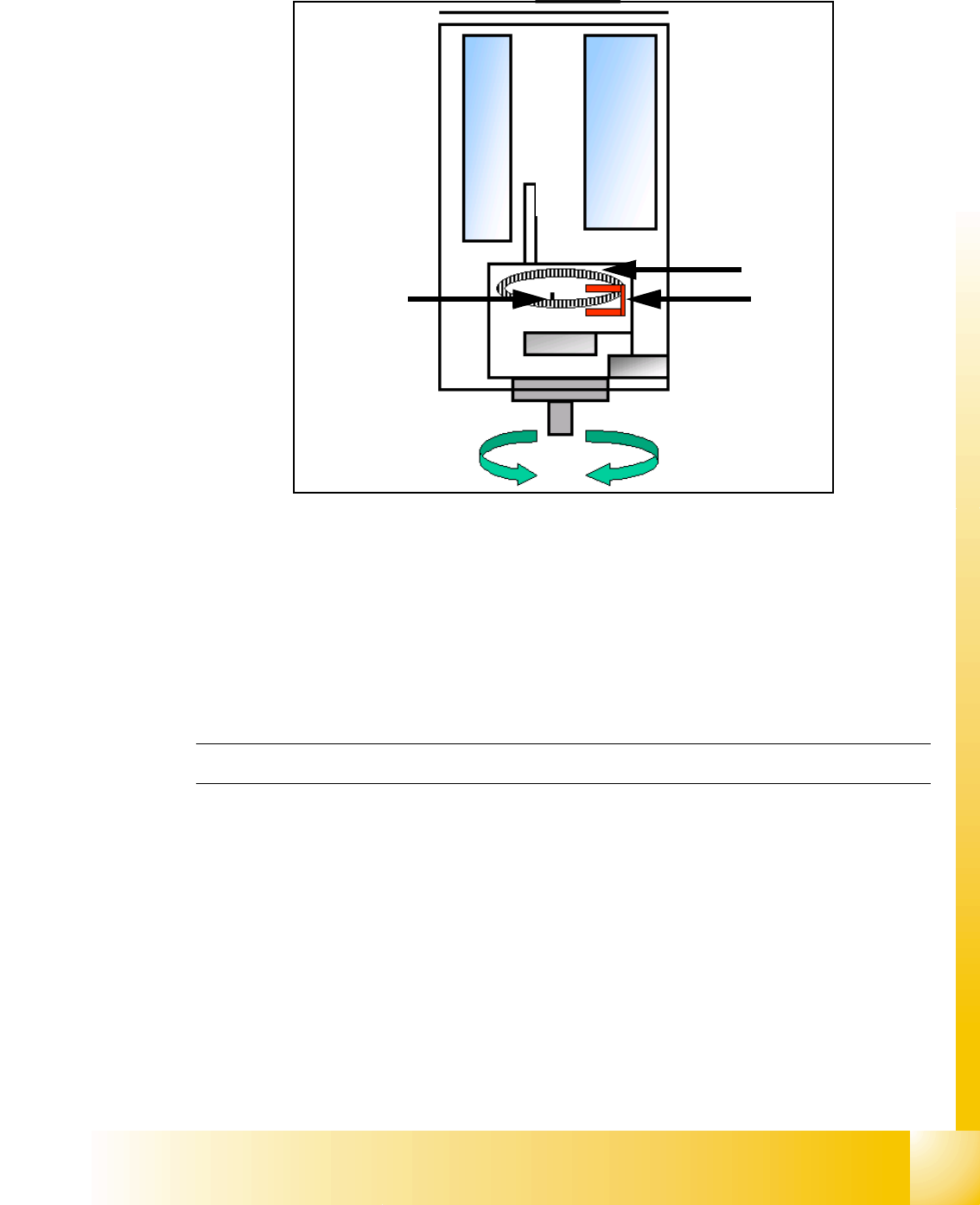
7.2.2 Reference run at D- axis
Fig. 7.2 - 3 Reference run D-axis
1. Incremental glass scale D-axis
2. Incremental encoder
3. Zero pulse on the incremental glass scale
Then the D-axis (turning axis) executes the reference run.
The D-axis runs to the zero pulse of the D- axis encoder. The zero point correction value is loaded.
Depending on the polarity the D-axis turns to reference position.
TWIN-head reference run finished! After that followed the refernce run of the Gantry.
7.2.3 Vacuum check
– After the machine is switched ON the CAN Bus prozessor will be started and therefore the
Vacuum-, Air kiss generator will be initialized. Neither vacuum or air kiss is on the nozzle.
– The Gantry axes move the TWIN-head to the reject position.
– Over the reject box the Vacuum-, Air kiss generator switch to air kiss to reject components and
check the air kiss.
– The Vacuum-, Air kiss generator is switchted to vacuum and the open vacuum threshold is
measured. (The closed vacuum threshold is taken from SITEST calibration.)
– The pressure air is adjusted to 0 bar.
– After this the height reference run started
2
3
1