SiplaceX4_en.pdf - 第330页
1 - 14 S tudent Guide SIPLACE X 7 T win-Head Edition 09/2005 14 7.3.4 Prep are pick up process module 2 7.3.4.1 Pick up component module 2 Pick up with module 1 finished – St art X / Y Axis to Pick up position at feeder …
1 - 13
Student Guide SIPLACE X
Edition 09/2005 7 Twin-Head
13
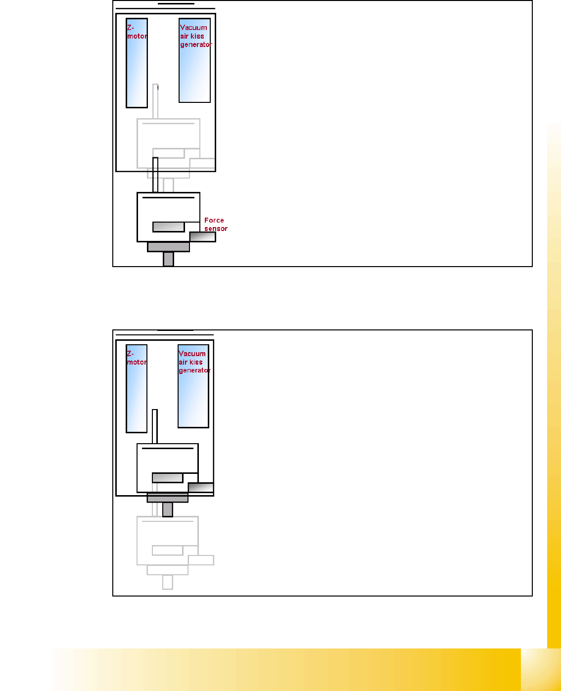
7.3.3.1 Pick up component module 1
– Z-Axis position downwards with Standard Pick up
mode at 2 N Pick up force.
– At contact with the component the force increase up
to the programmed value.
– At this force level the End signal is triggered and the
Vacuum controlling is activated.
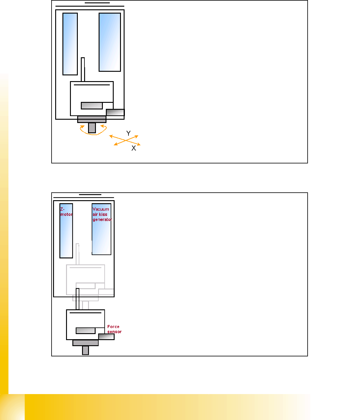
– When Vacuum threshold ‘Pick up’ is measured the Z-
Axis movement upwards start with Standard-position-
ing mode.
– communication to comp. table ‘index Feeder’ when
the Z-Axis reached the "safety height position.
– At end signal Z-Axis top -> Vacuum check ‘comp. on
nozzle’
– Turn with D-Axis the component to the placement an-
gle.
– Prepare pick up with module 2
1 - 14
Student Guide SIPLACE X
7 Twin-Head Edition 09/2005
14
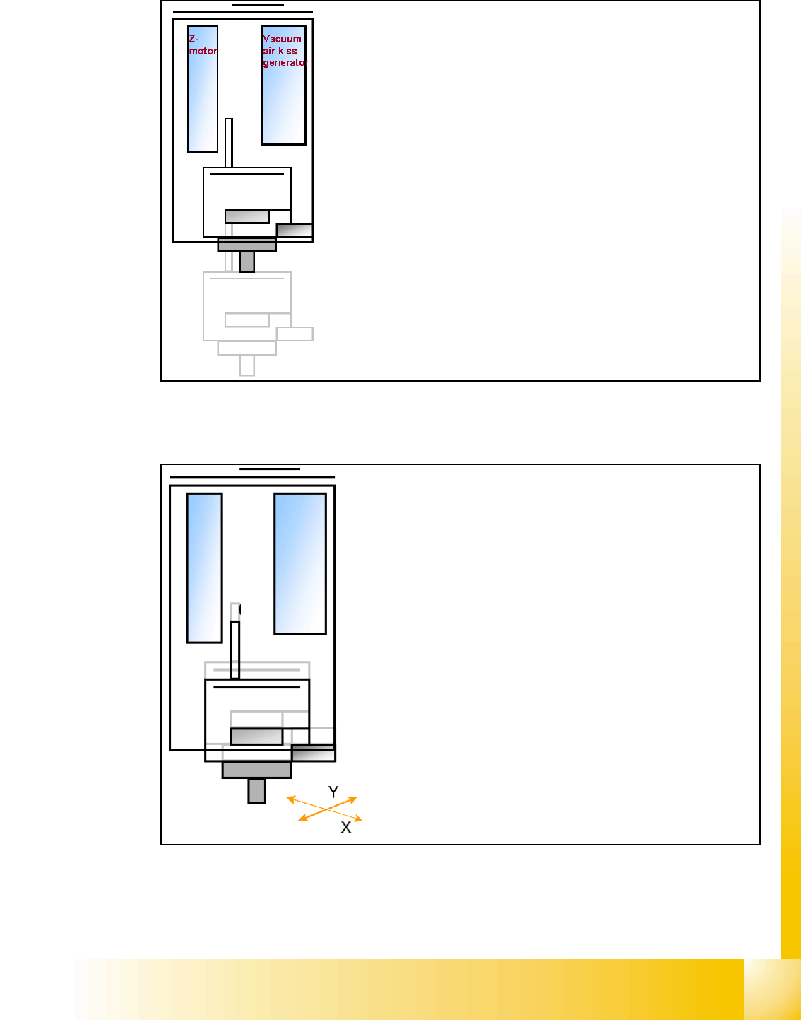
7.3.4 Prepare pick up process module 2
7.3.4.1 Pick up component module 2
Pick up with module 1 finished
– Start X / Y Axis to Pick up position at feeder
track.
– Start D2 Axis to set the Pick up angle during
X / Y positioning ..
– communication to comp. table ‘Feeder ready’
opens component flap.
Z-
M
o
t
o
r
D-Motor
– Z-Axis position downwards with Standard Pick up
mode at 2 N Pick up force.
– At contact with the component the force increase up
to the programmed value.
– At this force level the End signal is triggered and the
Vacuum controlling is activated.
1 - 15
Student Guide SIPLACE X
Edition 09/2005 7 Twin-Head
15
7.3.5 Component centering module 1 and 2
– When Vacuum threshold ‘Pick up’ is measured the Z-
Axis movement upwards start with Standard-position-
ing mode.
– Communication to comp. table ‘index Feeder’ when
the Z-Axis reached the "safety height" position.
– At end signal Z-Axis top -> Vacuum check ‘comp. on
nozzle’
– Turn with D-Axis the component to the placement an-
gle.
– Prepare optical centering with module 1
– Start X / Y Axis to move module 1 to camera position.
– Start Z-Axis to move Bottom side of comp. to focus level.
– ‘flash’ IC-camera illumination
– Move Z-Axis again upwards.
– centering 1st component (near placement angle) is finished
– Start X / Y Axis to move module 2 to camera position.
– Start Z-Axis to move Bottom side of comp. to focus level.
– ‘flash’ IC-camera illumination
– Move Z-Axis again upwards.
– centering 2nd component (near placement angle) is finished