SiplaceX4_en.pdf - 第334页
1 - 18 S tudent Guide SIPLACE X 7 T win-Head Edition 09/2005 18 Please Note
1 - 17
Student Guide SIPLACE X
Edition 09/2005 7 Twin-Head
17
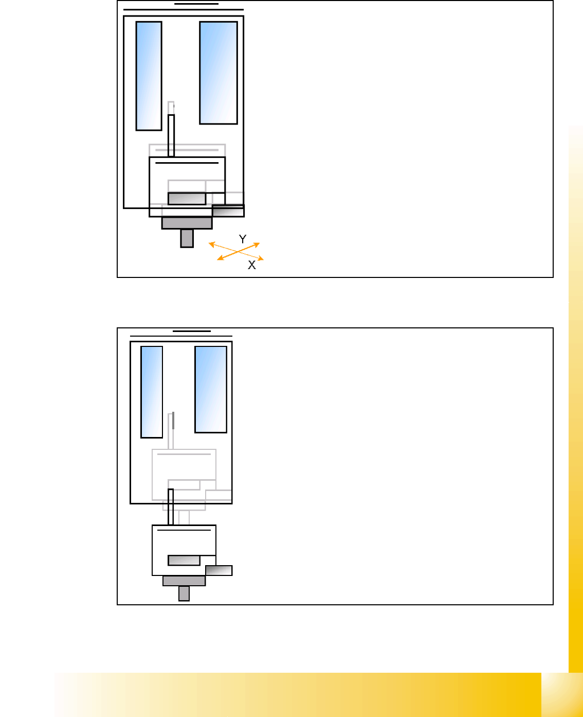
7.3.7 Prepare placement 2nd component
7.3.7.1 Place 2nd component
– Start X / Y Axis to the real placement position (inclusive cor-
rection coordinates).
– Start D- Axis to correct component to precise placement an-
gle
– Z-Axis position downwards with Standard profile (ôr any
other programmed profile up to 15N)for placement force 2 N.
– The Force increase up to the programmed level after contact
of the component on the PCB.
– With this Force signal the End signal is set. The air kiss
control is activated too.
– At Air kiss level for placement Z-Axis move upwards with
Standard profile.
– The next Pick up sequence is prepared for module 1.

1 - 19
Student Guide SIPLACE X
Edition 09/2005 7 Twin-Head
19
7.4 Adjustments
7.4.1 Description of the boards on the Twin- Head
All described adjustments in this chapter are head specific and are necessary here for the
Twin Head.
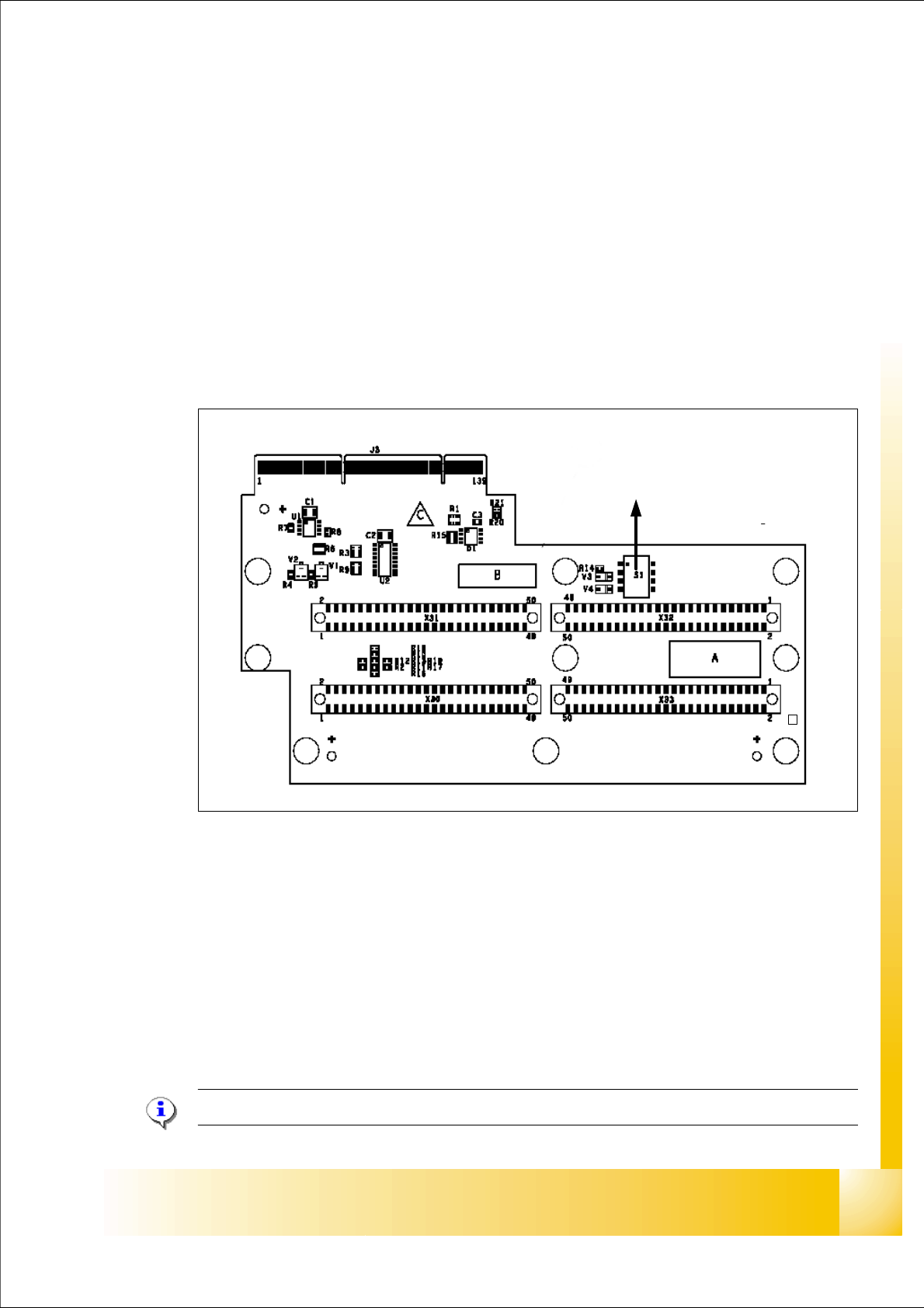
7.4.1.1 Head adapter Twin- Head
The head adapter board connects the head interface from the bottom side directly.The main board
of Twin head segment 1 and 2 is connected via ribbon cable to the adapter board. This head
adapter must be changed for head modularity, if you use a C&P head.
Fig. 7.4 - 1 Head adapter Twin head
Please Note: The ribbon cable sets for the Twin head segment 1and 2 are different.
(1) Connector Z-Axis Twin head 1 (2) Connector D-Axis Twin head 1
(3) Connector DP-Axis Twin head 2 (4) Connector Z-Axis Twin head 2
(5) DIP Switch (without function) (6) LED C167 = ON TQM Module on the head
interface C500 --> OK
(to 5) PP1 Boot CAN Processor Twin Segm. 1 (to 5) PP1 Reset CAN Processor Twin Segm. 1
(to 5) PP2 Boot CAN Processor Twin Segm. 2 (to 5) PP2 Reset CAN Processor Twin Segm. 2
1
24
3
5
C167
6