SiplaceX4_en.pdf - 第336页
1 - 20 S tudent Guide SIPLACE X 7 T win-Head Edition 09/2005 20 7.4.1.2 T win- Head main board The main board is mounted directly on the top of the frame of the TWIN-hea d. This board is con- nected to the head adapte r …
1 - 19
Student Guide SIPLACE X
Edition 09/2005 7 Twin-Head
19
7.4 Adjustments
7.4.1 Description of the boards on the Twin- Head
All described adjustments in this chapter are head specific and are necessary here for the
Twin Head.
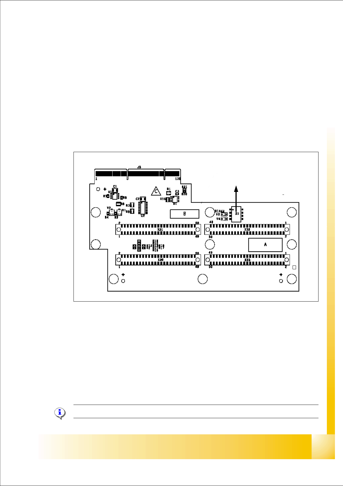
7.4.1.1 Head adapter Twin- Head
The head adapter board connects the head interface from the bottom side directly.The main board
of Twin head segment 1 and 2 is connected via ribbon cable to the adapter board. This head
adapter must be changed for head modularity, if you use a C&P head.
Fig. 7.4 - 1 Head adapter Twin head
Please Note: The ribbon cable sets for the Twin head segment 1and 2 are different.
(1) Connector Z-Axis Twin head 1 (2) Connector D-Axis Twin head 1
(3) Connector DP-Axis Twin head 2 (4) Connector Z-Axis Twin head 2
(5) DIP Switch (without function) (6) LED C167 = ON TQM Module on the head
interface C500 --> OK
(to 5) PP1 Boot CAN Processor Twin Segm. 1 (to 5) PP1 Reset CAN Processor Twin Segm. 1
(to 5) PP2 Boot CAN Processor Twin Segm. 2 (to 5) PP2 Reset CAN Processor Twin Segm. 2
1
24
3
5
C167
6
1 - 20
Student Guide SIPLACE X
7 Twin-Head Edition 09/2005
20
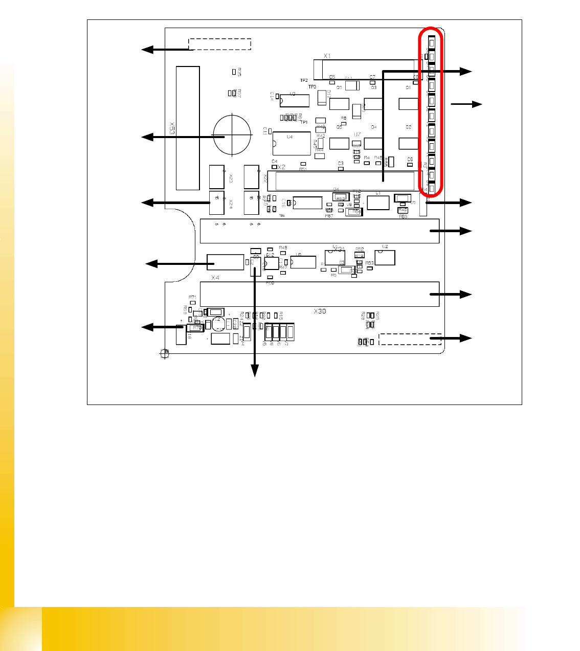
7.4.1.2 Twin- Head main board
The main board is mounted directly on the top of the frame of the TWIN-head. This board is con-
nected to the head adapter via two ribbon cable (one ribbon cable for each axis). The difference
to the Twin Head on the HF machine is now, that we don‘t use the 16 Bit Can Prozessor on each
main board. The control of both Twin heads will make the Can Prozessor on the head interface
C500.
Fig. 7.4 - 2 Main board at TWIN-head (00352833-xx)
1. Connector for the 16 Bit CAN Bus Processor only for HF-machine, in future we use only the 16
Bit Processor on the head interface on HF/X machine (Control the analog or digital vacuum-
generator).
2. LED´S signs (Description from top to bottom/ on the board in German language)
– D8 without function (retract unit)
– D7 KLEMM: (retract unit)
– D6 BERO: Z-axis top (not used)
– D1 DRUCK: at the moment not used/ Z-Druck (Z-Pressure)
2
3
4
5
8
6
9
10
11
12
X21
X8
7
1
1 - 21
Student Guide SIPLACE X
Edition 09/2005 7 Twin-Head
21
– D2 KLEMM: Clamping Z-axis (yellow) LED off, retract unit is at top position
– V2 V_SP: shows the power supply 15V for the track signals D-Axis
The LED ‘s V2/V3 are OFF if the jumper(X54) ON and the old force measurement board is
mounted. For Twin Heads with a new force measurement board (in future) the 15 V will con-
trolled directly on the main board. D.h The jumper have to OFF and the LED‘s should be
ON.
– V3 15V_: 15 V for the track signal D - axis at the moment OFF.
– V1 TEMP: Temperature monitoring Z-axis linear motor (red) LED OFF, is ok.
– D14 ALARM: Alarm output for the vacuumgenerator (red LED ON vacuumgenerator defect)
– D9 DRUCK: at the moment not used/ Z-Druck (Z-Pressure)
– D10 24V+: green LED ON 24V for the vacuumgenerator
3. X54 Jumper at the moment ON with the new force measurement board chage to OFF
(see LED V2/V_SP)
4. Connectors to the head adapter
5. Connectors to the head adapter
6. X8: Flex-Cable (Signals: Tracksignals D-Axis, Power supply Z-Axis/D-Axis, Z-Temperature
and, SPI Bus)
7. EEPROM storage the head specific data ( Head exchange, Reference run)
8. Power supply 15 V for the Track signals D-Axis (at the moment deactivated via the jumper X54)
9. X4 Connector track signals Z-axis
10.Connector pneumatic valve (retract unit)
11.Hole for pneumatic pipe to the vacuum generator
12. X21 connector vacuum generator
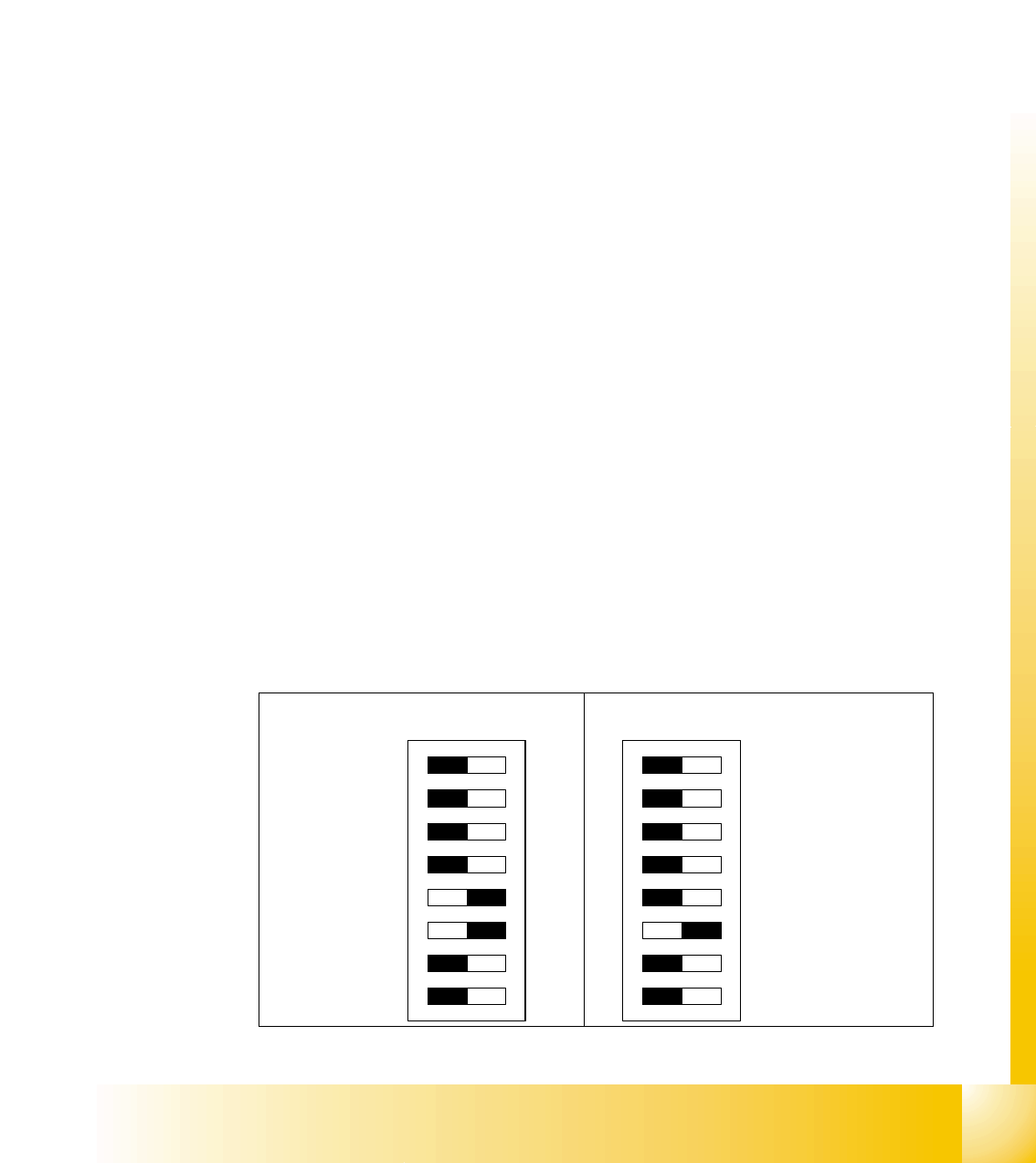
7.4.1.3 Vision control board "IC camera"
The vision control board is installed in sector 2 and sector 4 (X2) for the stationary cameras.
ON
78123456
ON
78123456
DIP Switch for Sector 4 (Sub Distribu-
tor)
DIP Switch for Sector 2 (Main Distributor)