SiplaceX4_en.pdf - 第34页
1 - 10 S tudent Guide SIPLACE X 2 Overview Edition 09/2005 10 2.2.1 Power supply unit The main power supply u nit is mounted on a compac t rack unit and located on the left side of the middle section. When viewed from th…
1 - 9
Student Guide SIPLACE X
Edition 09/2005 2 Overview
9
2.2 Overview of Units
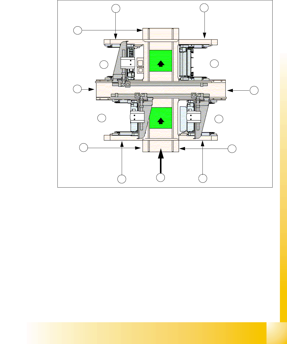
Fig. 2.2 - 1 Top view Siplace X3
Key
(1) Sector 1 (2) Sector 2 (main distributor)
(3) Sector 3 (4) Sector 4 (subdistributer)
(5) Transport direction (6) Pneumatic unit & control unit conveyor
(7) Component changeover table location (8) Computer unit
(9) Location for component changeover table
or MTC 2 for BB 2
(10) Location for component changeover table
or MTC 2 for BB 1 (MTC only X2)
(11) Axis unit in PA 1(BB1) (12) Axis unit in PA 2
(13) Power supply unit
1
2
8
3
5
6
4
7
7
9
10
11
BB 1
BB 2
13
12
1 - 10
Student Guide SIPLACE X
2 Overview Edition 09/2005
10
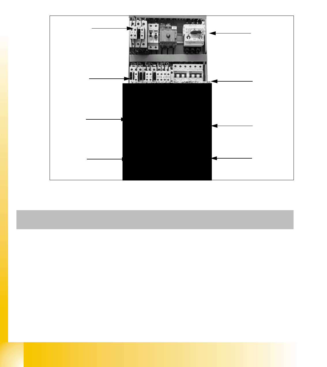
2.2.1 Power supply unit
The main power supply unit is mounted on a compact rack unit and located on the left side of the
middle section. When viewed from the outside, only the red main power switch is visible.
A lockable door prevents access to the unit.
2.2.1.1 Overview of Voltages in the Power Supply Unit
Fig. 2.2 - 2 Power supply at the front
K1
K2 / K3 / K4
K6
K5
F1/F14
F2 / F10 / F6 / F8 /
F12 / F13
F4 / F7
F11 / F5
Q1 / Q2
Component
assembly
Designation Contact Voltage
X100 Terminal strip for power supply L1, L2, L3 3 x 204 VAC / 3 x 380 VAC
3 x 400 VAC / 3 x 415 VAC
X102 Service socket 115 VAC / 220 VAC / 230 VAC / 240
VAC
Q1 Main switch 1, 3, 5 and
2, 4, 6
3 x 204 VAC / 3 x 380 VAC
3 x 400 VAC / 3 x 415 VAC
Q2 Motor circuit-breaker 1, 3, 5 and
2, 4, 6
3 x 204 VAC / 3 x 380 VAC
3 x 400 VAC / 3 x 415 VAC
K1 Main contactor 1, 3, 5 and
2, 4, 6
3 x 204 VAC / 3 x 380 VAC
3 x 400 VAC / 3 x 415 VAC

1 - 11
Student Guide SIPLACE X
Edition 09/2005 2 Overview
11
K2 Contactor (voltage built-up of
the intermediate circuit voltage
for X/Y/Star axes)
1, 3, 5 and
2, 4, 6
3 x 177 VAC
K3 Contactor (voltage built-up of
the intermediate circuit voltage
for X/Y/Star axes)
1, 3, 5 and
2, 4, 6
3 x 177 VAC
K4 Contactor (voltage built-up of
the intermediate circuit voltage
for X/Y/Star axes)
1, 3, 5 and
2, 4, 6
3 x 177 VAC
K5 Contactor ( software release is
ON)
A1 (+) – A2
(-)
1.2
3.4
5.6
24VDC
24 VDC
against ground
24 VDC against ground
24 VDC against ground
K6 (SSK) Contactor unit L+, X3, X5 24 VDC against ground
F1 Fuse for service socket; 1-pol. 1, 2 115 VAC / 220 VAC
230 VAC / 240 VAC
F2 Fuse for component table;
3-pol.
1, 3, 5 and
2, 4, 6
3 x 36 VAC
F4 Fuse for X-/Y-axis;
3-pol.
1, 3, 5 and
2, 4, 6
3 x 177 VAC
F5 Fuse for star axis;
1-pol.
1, 2 145 VDC
against ground
F6 Fuse for Z-/DP-axis; DP-drive
C&P20 head, 1-pol.
1, 2 39 VDC against ground
F8 Fuse for PCB conveyor;
1-pol.
1, 2 33 VDC against ground
F10 Fuse for rectifier V7 and V70;
3-pol.
1, 3, 5 and
2, 4, 6
3 x 39 VAC
F11 Fuse for inrush current limita-
tion board; 1-pol.
1, 2 33,6 VDC
against ground
F12 Fuse for illumination
1-pol.
1, 2 52 VDC against ground
F13 Fuse for monitor; 1-pol. 1, 2 26 VDC against ground
F14 Fuse for Y-motor fan; 1-pol. 1, 2 26 VDC against ground
Component
assembly
Designation Contact Voltage