SiplaceX4_en.pdf - 第341页
1 - 25 S tudent Guide SIPLACE X Edition 09/2005 7 T win-Head 25 Please Note: With the SW 505 the ZPC value is valid for the TWIN-module 1 and 2. Here the value can b e en- tered without modification. For TWIN-module 1, t…
1 - 24
Student Guide SIPLACE X
7 Twin-Head Edition 09/2005
24
7.4.3 Parameter Twin- Head
You find a label with parameters for the TWIN-head module which must be entered in the Sitest
during initial set-up or after replacement of a TWIN-module.
7
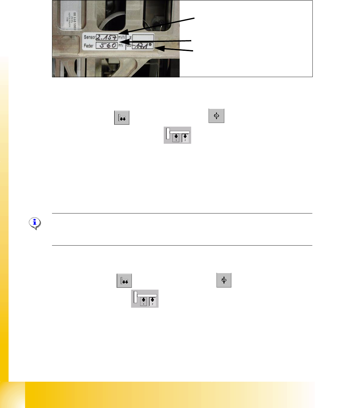
Fig. 7.4 - 5 Label with parameter for TWIN-head modul
Parameter force sensor and spring pre-tension 7
Sitest: 7
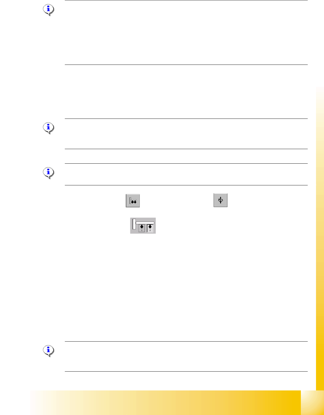
➠ Select "Twin Head" ==> Select "axis functions"
➠ Select the appropriate Twin module)
➠ Select the checkbox "Z-axis".
➠ Select "Parameter..." and enter the values
"Force sensor calibration value" in [mV/V].
This value is always smaller than 3.0 [mV/V] .
and "Spring pre-tension" in [mN]. This value is between 300 and 700 [mN] .
➠ Wrong settings for the twin module will result in inaccurate placement or pick-up force (1 bis
15N).
Please Note:
The adjusting screw (fine thread) for the spring pre-tension MUST NOT be adjusted - otherwise a
replacement of the P&P module might be necessary.. 7
Zero point correction (ZPC) D-Axis 7
Sitest: 7
➠ Select "Twin Head" ==> Select "Axis functions"
==> Select the Twin module
7
==> Aktivate the checkbox "D-axis" 7
==> Select "Positions..." 7
==> Deaktivate the checkbox "digits" 7
==> Enter the ZPC value in 1/100 degrees into the 2. row " ZPC from the label" and select "ac-
cept".
7
Sensor (Parameter for strain gauges,force
sensor)
Feder (Spring pre-tension)
dp (zero point correction D-axis)
1 - 25
Student Guide SIPLACE X
Edition 09/2005 7 Twin-Head
25
Please Note:
With the SW 505 the ZPC value is valid for the TWIN-module 1 and 2. Here the value can be en-
tered without modification. For TWIN-module 1, the station software calculate automatically 180
degrees to the value from TWIN-module2 .
Example for the value shown on the label above:
-17100 ( module 2) resp.
900 ( module 1) 7
➠ Perform a reference run for the D-axis.
➠ Don’t forget to perform the calibration of the D-axis.
Zero point correction (ZPC) Z-Axis 7
Please Note:
Enter the standard values for the Z-axis, only if the reference run or the calibration head height
not successfully. 7
Please Note:
Please make sure that 517 nozzle are on the TWIN-Head. 7
Sitest: 7 ➠ Select "TWIN Head" ==> Select "axis functions"
Select the TWIN-module , activate "Z-Axis"
==> Select "Positions..." and enter the following values: (switch of ’position in Digit’
(deselect ’display in digit’ radio button)
Maximum position: 57500 µm 7
Minimum position: -2000 µm 7
Zero point correction: 0 µm 7
7
==> Perform a head height calibration (ZPC for the Z-axis).
==> Perform a reference run for the whole machine before you continue calibration.
Please Note:
The zero point correction, max.- and min.- travel range of the Z-Axis will determined when you
calibrate the head height of the twin module. 7
1 - 26
Student Guide SIPLACE X
7 Twin-Head Edition 09/2005
26
7.4.4 Calibrate D-Axis
Please Note:
The exact zero point correction (ZPC) of the D-axis is calibrated on the SIPLACE HF/HF3 by
means of a
calibration nozzle automatically.
A correct calibration can only be expected if the angle differs less than +/- 5 degrees from the ex-
act value - prior to the following calibration steps. 7
➠ Put the calibration nozzle for the TWIN Head by hand on the segment of the appropriate Twin
module. Make sure that the two adjust pins of the nozzle fit correctly.
➠ Perform an axis reference run for the D-axis.
➠ Check the alignment of the nozzle:
The drilling on the calibration nozzle must show to the
middle (SW 505 or higher) of the ma-
chine (504 to machine outside) and the nozzle must be aligned parallel to the PCB conveyor.
➠ Assign the nozzle "516" for the P&P module to be calibrated:
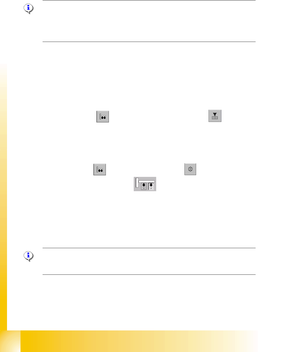
Sitest: 7 ==> Select "Twin Head" ==> Select Nozzle changer head functions 7
==> Select the appropriate "segment" out of the list. 7
==>Select "Edit" ==> select "516" and "accept". 7
==> Acticate "selected segment". 7
==> Select "confirm exchange".
7
Sitest: 7 ➠ Select "Twin Head" ==> Select "calibration functions"
➠ Select the appropriate Twin module
➠ Select "calibrate zero point DP-axis".
➠ mount ZP-calibration nozzle
➠ mount the calibration nozzle manually on respective segment.
The ZPC will be calculated automatically by means of angle determination of the nozzle out-
line.
Repeat this step until the new value deviates less than +/- 0,01° from the old value.
Please Note:
If the calibration not successully, you can determined the zero point correction manually see chap-
ter 7.4.4.1 .Then you must calibrate the ZPC with the calibrate nozzle. 7