SiplaceX4_en.pdf - 第346页
1 - 30 S tudent Guide SIPLACE X 7 T win-Head Edition 09/2005 30 7.4.6.4 Check the pressure tightness of the vacuum sy stem ➠ S tart SITEST . ➠ Move the gantry so that you can easily reach th e nozzle of the T win Head wi…
1 - 29
Student Guide SIPLACE X
Edition 09/2005 7 Twin-Head
29
7
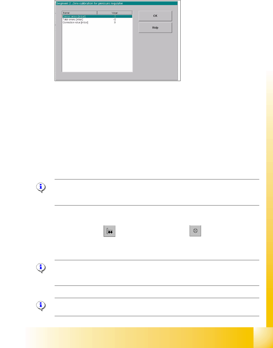
Fig. 7.4 - 7 Correction values after zero calibration
➠ Press "OK".
The correction value will be accepted - now the reference value equals the ambient pressure.
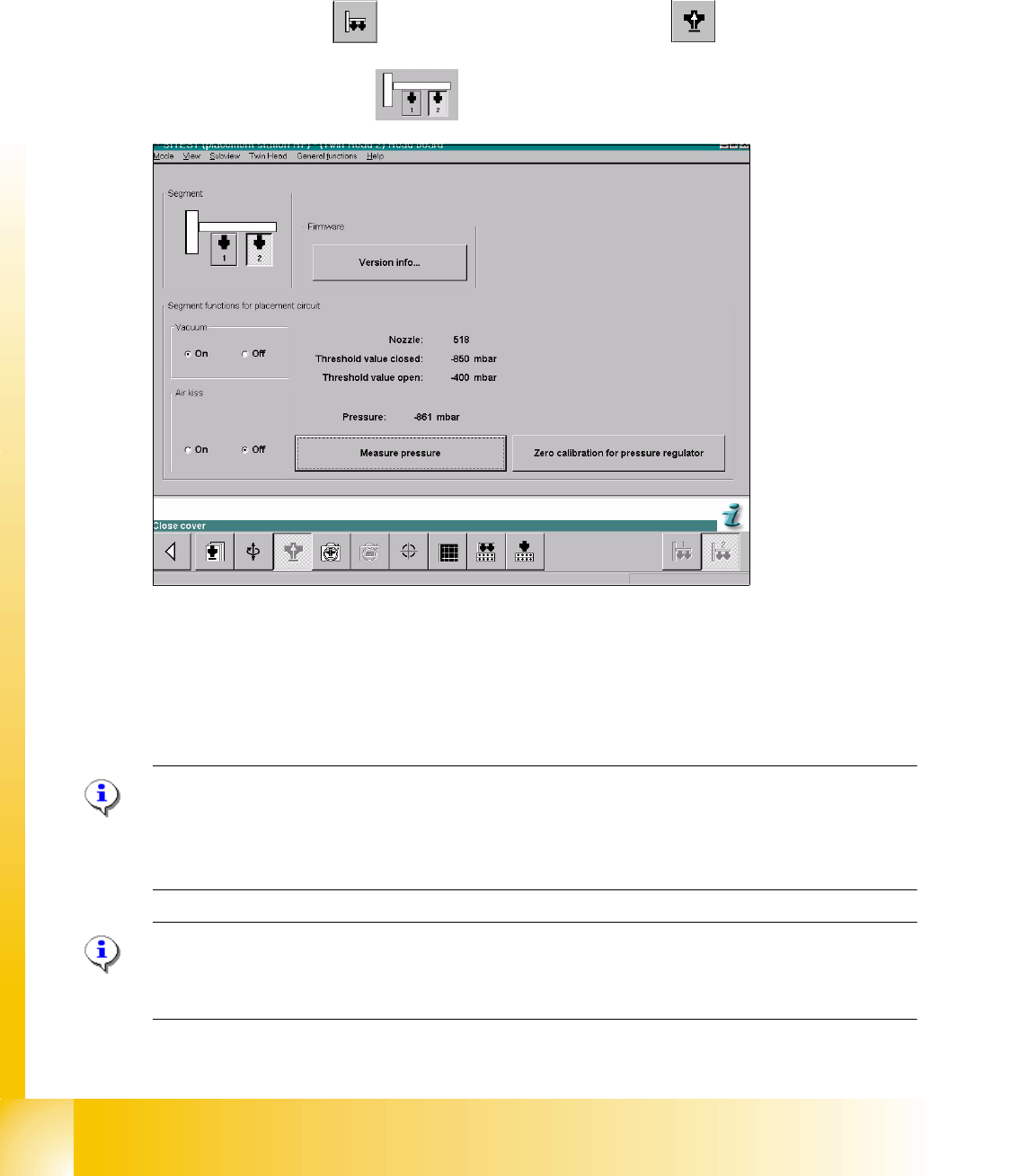
7.4.6.2 Check the Zero calibration of the vacuum generator
Sitest: 7
Select "Twin head" ==> Select "Head board" ==> Press the button "Measure pressure"
If you check the zero calibration the preconditions are "Vacuum is OFF" and "Air kiss is OFF"
(siehe Fig. 7.4 - 6).
Please Note
The pressure deviation to the ambient pressure in the case of 0 - mbar calibration should not
exceed for ± 10 mbar. 7
7.4.6.3 Calibrate closed vacuum
Sitest: 7
➠ Select "Twin Head" ==>Select "calibration functions"
==> Select Sie "Calibrate closed vacuum"
Please Note:The value for "closed vacuum" will be measured automatically for both Twin mod-
ules.
In the dialog window the former and the new values are shown. 7
Please Note:
The indication "closed vacuum" equals "Threshold value closed" in SITEST. 7
1 - 30
Student Guide SIPLACE X
7 Twin-Head Edition 09/2005
30
7.4.6.4 Check the pressure tightness of the vacuum system
➠ Start SITEST.
➠ Move the gantry so that you can easily reach the nozzle of the Twin Head with one and the
keyboard with the other hand.
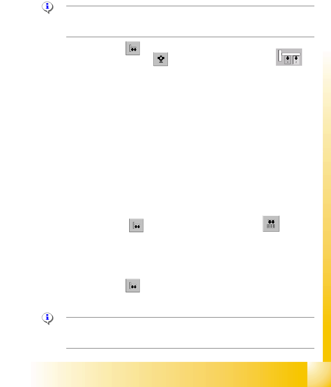
Sitest 7 ➠ Select "Twin head" ==> Select "Head board functions"
==>Select Twin module
fig. 7.4 - 8 SITEST functions head board functions
➠ Switch "on" the vacuum.
➠ Close the nozzle of the appropriate P&P module (e.g. by sealing it with your finger tip).
➠ Select "Measure pressure".
➠ The displayed value should be close to the "Threshold value closed".
Please Note:
"Threshold value closed" (or closed vacuum) defines the maximum vacuum.
"
Threshold value open" defines the maximal allowable vacuum value for the specific nozzle type
- in case that no nozzle is setup, the value "0" is shown.
Please Note:
The value "Vacuum closed" will be determined in the menue "Calibrate Twin head"==> "Vacuum
closed calibrate".
1 - 31
Student Guide SIPLACE X
Edition 09/2005 7 Twin-Head
31
7.4.6.5 Check the "Air kiss" pressure
➠ Start SITEST.
➠ Move the gantry so that you can easily reach the nozzle of the Twin Head with one and the
keyboard with the other hand.
Please Note:
The value for the "Air kiss" pressure can be edited between 0 and 400 mbar. Standard value (only
for SITEST): 400 mbar 7
➠ Select "Twin Head"
Sitest: 7 ➠ Select "Head board functions" ==> Select the Twin module (segment)
➠ Switch "on" the air kiss.
➠ Close the nozzle of the appropriate Twin module (e.g. by sealing it with your finger tip).
➠ You can edit and modify the value for the forced air pressure or leave the standard value.
➠ Select "Measure pressure".
➠ The measured value should correspond (approx.) with the given value.
7.4.7 Calibrating the Twin- Head
During initial set-up or after replacement of a Twin module the Twin Head must be calibrated. The
Offset between TWIN Segment and PCB-camera center is meassured.
7
➠ Put the nozzles 517 by hand on the segments of the P&P modules.
➠ Make sure that the first nozzle from the garages are empty and depend on this the filling
level from the nozzle changer are edited, this is necessary for the calibration of the pick-up
height.
➠ Enter the nozzle "517" for both Twin modules as active nozzle on the Twin Head:
Sitest: 7 ==> Select "Twin Head" ==> Select "nozzle changer head functions" 7
7
==> Select the appropriate "segment" out of the list. 7
==> Select "Edit" ==> Select "517" and "accept". 7
==> Activate the checkbox "selected segment". 7
==> Select "Confirm exchange". 7
7
➠ Select "Twin Head" ==> Select "Calibrate machine"
==> Activate only "Twin Head" of the appropriate placement area.
==> Select "Start".
Please Note: The following points are calibrate automatically:
- MA-Zero point, PCB Camera, Calibration tool position, Head height, TH calibration Offset modul
1and 2, IC Camera, (option FC Camera) Nozzle changer. 7