SiplaceX4_en.pdf - 第353页
1 - 37 S tudent Guide SIPLACE X Edition 09/2005 7 T win-Head 37 7.6 Axis control 7.6.1 Overview Axis co ntrol Z- and D-Axis The closed-loop control system for control of th e head axes consists of the followin g part s. …
1 - 36
Student Guide SIPLACE X
7 Twin-Head Edition 09/2005
36
7.5.2.3 Description of the functions
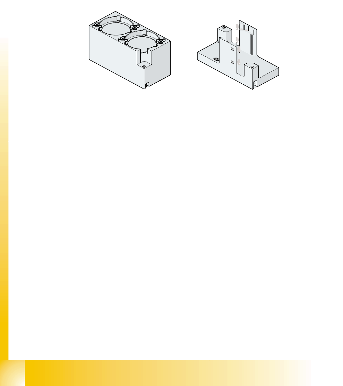
The magazine for standard nozzles has 1 positioning fiducial for position detection, while the mag-
azine for special nozzles/grippers has two positioning fiducials. The nozzles are fixed by balls in
the holder. They are then either locked for return or released for pick up, depending on the direc-
tion of rotation of the DP axis.
Fig. 7.5 - 4 Magazine for standard- and special nozzles
Legend
Position of the nozzle in the magazines 7
(1) Standard magazine (2) Positioning fiducia
(3) Nozzle holder (4) Magazine for special nozzles
(5) Nozzle holder (6) Balls for lifting the nozzles
1 - 37
Student Guide SIPLACE X
Edition 09/2005 7 Twin-Head
37
7.6 Axis control
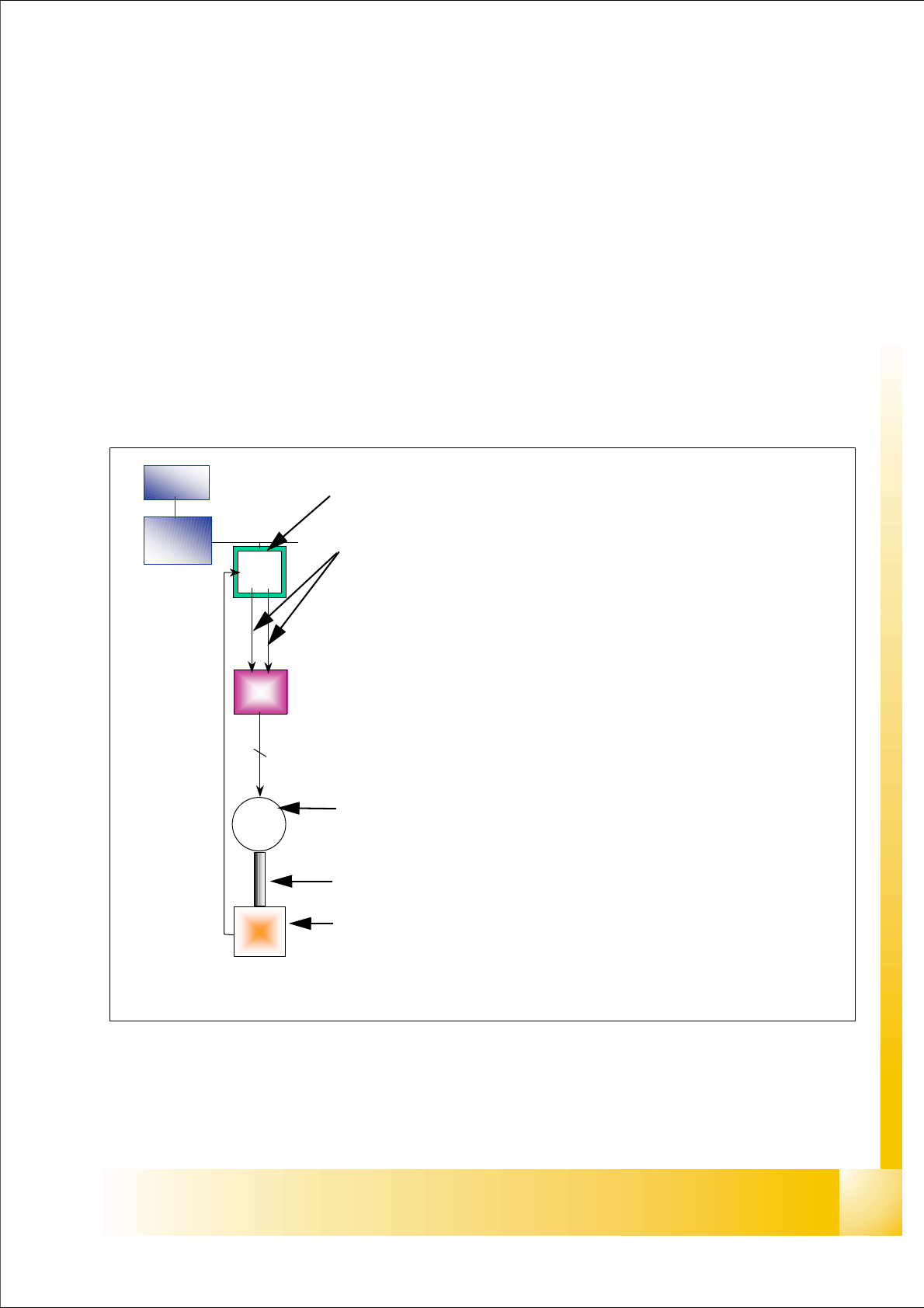
7.6.1 Overview Axis control Z- and D-Axis
The closed-loop control system for control of the head axes consists of the following parts.
– Axis controller with VC 3 Controller
– Servo card (SDS)
– Motor
– Measuring system (Incremental- scale and -encoder)
Between the head axes, some differences which will be explain later in this chapter.
Fig. 7.6 - 1 Example: Axis control D-axis
MC
COM
board
VC 3
cont
Servo
ampli.
M
2 ~
Enco-
der
2
Axis card A363 with VC 3 Controller (VC = Velocity Commutation)
Control signals I
nom "W" and I nom "U"
LED‘s on the Servo amplifier:
– Power supply ON
– Servo enable, if the the enable signal from the axis board available.
– Display RMS current limiter shorter than 2,5 s.
– Error: Overvoltage, -current, -temperature or Nominal current-overstep-
ping longer than 2,5 sec.
Servo board control directly the motor.
2 Phase AC motor for D Axis.
3 phase AC linear motor for Z-Axis
Between the motor and the incremental encoder exist a fixed mechanical
combination.
Incremental encoder: trace the exact position of the axis via track signal.
1 - 38
Student Guide SIPLACE X
7 Twin-Head Edition 09/2005
38
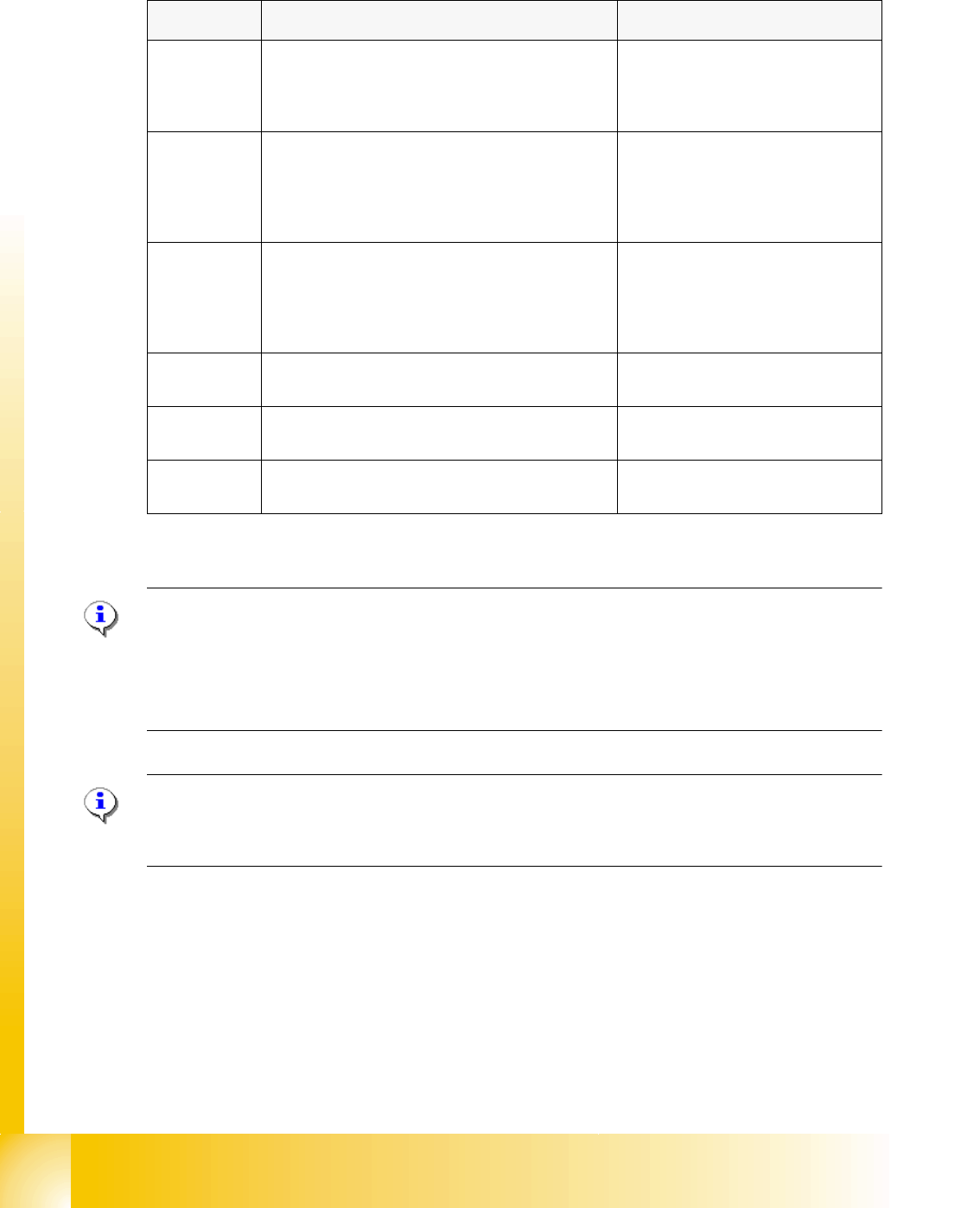
7.6.1.1 Overview positioning time for the Twin- head
7
Please Note: (Z-Axis)
The positioning time for the Z-axis with the current mode and force sensor have no direct inference
to the function.
In order to check this functions please use an oscilloscope and for the mode force sensor a special
PCB board with force sensor. 7
Please Note: (D-Axis)
The positioning time for the left and right rotation of the D-axis could be a little bit different, but this
time is not critical in case of the placement sequence of the TWIN- head. 7
Axis Mode / Distance / Positioning time
Z Positioning absolut,
free space /
Distance 100000 digits = 50000 µm
(Resolution 0,5µm)
84ms +/-3ms
Z Current mode (to measure force)
into calibration tool pocket,
518 nozzle
Distance 92000 digits =46000 µm,
force 2N
ca. 240ms *
*see note below
Z Force sensor (o measure force)
into calibration tool pocket,
518 nozzle
Distance 46000 µm,
force 13N
ca. 240ms *
*see note below
D 10000 digits = 10 degree 90ms +/-10ms*
*see note below
D 90000 digits = 90 degree 150ms +/-20ms*
*see note below
D 180000 digits = 180 degree 190ms +/-20ms*
*see note below
Table 7.6 - 1 Positioning time for TWIN- head