SiplaceX4_en.pdf - 第356页
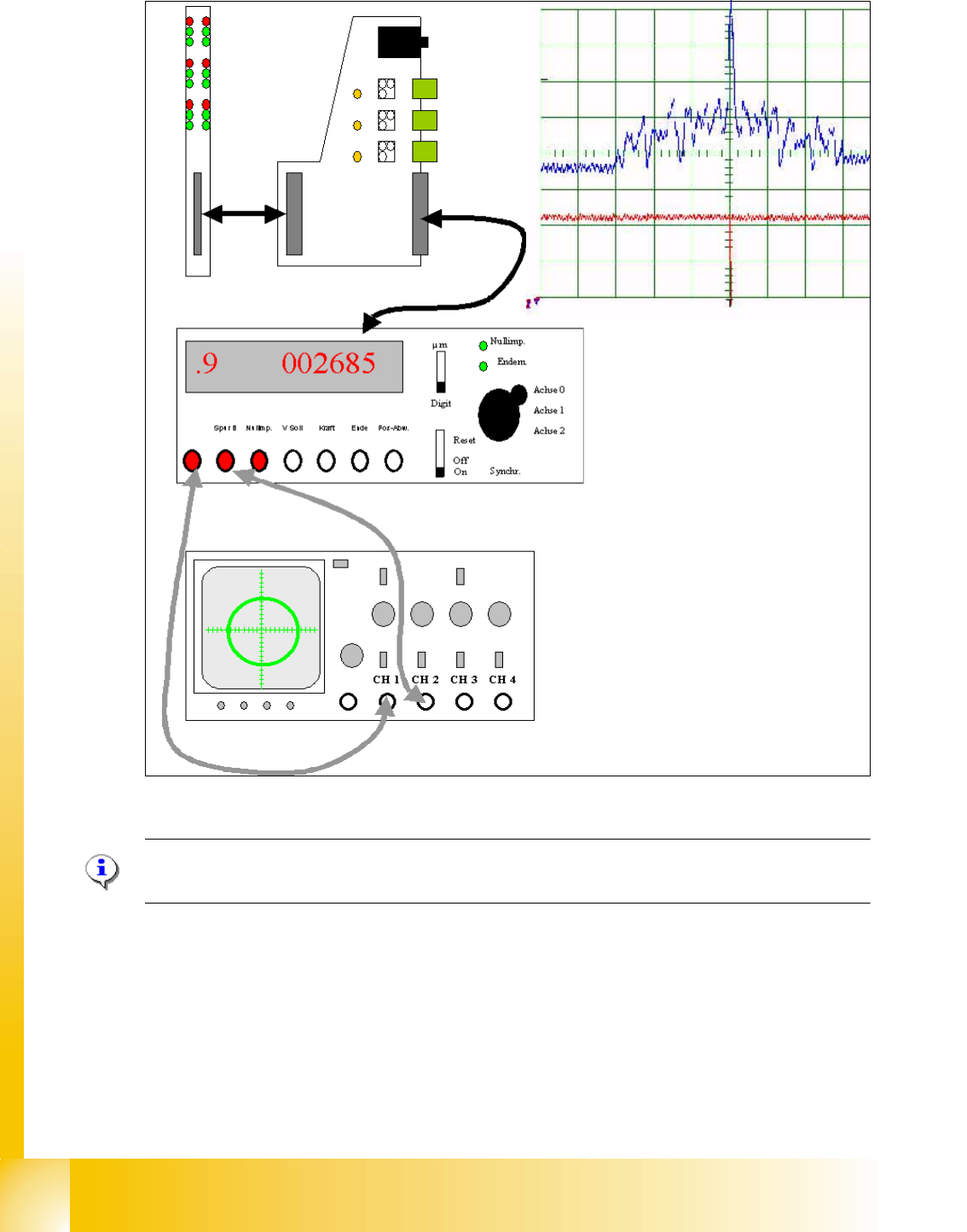
1 - 40 S tudent Guide SIPLACE X 7 T win-Head Edition 09/2005 40 7 Fig. 7.6 - 3 Digital track signals TWIN- head axes at axis test box Please Note: The Zero pulse at axis tester is inverted to th e digital zero pulse from…
1 - 39
Student Guide SIPLACE X
Edition 09/2005 7 Twin-Head
39
7.6.2 Track signals head axes
The track signals undertake the main control function in the case of the new drive concept of the
HF machine. They are responsible for the exact and precise positioning of the axes and are used
as only response of the closed-loop control system so that the track signals have an important
influence on dynamics of the axes.
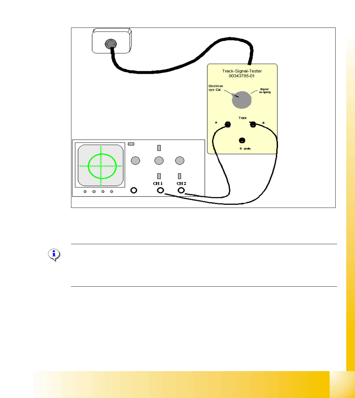
7.6.2.1 Test set up
Fig. 7.6 - 2 General test set up to check the analoge track signals TWIN- Z-axis
The analoge track signals of the TWIN- head Z-axes are measurable on the incremental encoder.
Please Note:
The digital track signals of the TWIN- head can only be measured on the axis test box.
The track signals of theTWIN head D-axes can only be measured as digital signals on the axis
test box. 7
1 - 41
Student Guide SIPLACE X
Edition 09/2005 7 Twin-Head
41
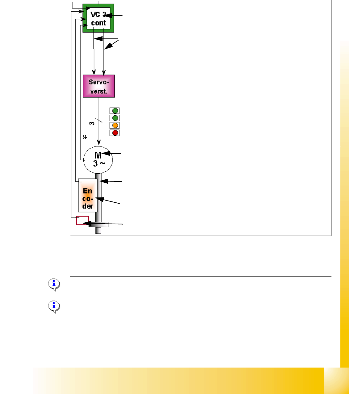
7.6.3 Axis control Twin- Head Z-axis
The Z axis is driven with a 3 phase AC linear motor with an intermediate circuit voltage of 60V.
The control of the axis occurred with two control signals of the VC3 (dephasing 120°) controller
I
nom "W" and I nom "U". The third phase is calculated at Servo amplifier.
Fig. 7.6 - 4 Axis control Z-axis TWIN- head
7.6.3.1 Check the dynamic of Z-axis
Please Note:
For detailed notes to check the axis dynamic, please use the "Adjustment manual".
7
Please Note:
Before adjusting the axes, ensure that the machine has reached its operating temperature.
Switch the machine on at least 30 minutes before you begin work.
Axis board A363 with VC 3 Controller (VC = Velocity Commutation)
Control signals I
soll "W" and I soll "U"
Servo board control directly the linear motor, Intermediate (DC) voltage cir-
cuit is 250V.
LED‘s on Servo board:
– Power supply ON
– Servo enable, it the enable signal from the axis board.
–Display I
RMS limit shorter than 2,5 s.
– Error: Over voltage, -current, -temperature longer than 2,5 sec.
3 Phase AC linear motor with integreted temperatur sensor.
Between motor and incremental scale exist a fixed mechanically connec-
tion.The incremental encoder is fixed on the frame of the TWIN- head.
Incremental encoder: Transmitted the correct position to the axis board and
is the only feedback signal to control the motor (Track signals).
Force sensor