SiplaceX4_en.pdf - 第366页
1 - 50 S tudent Guide SIPLACE X 7 T win-Head Edition 09/2005 50 Notes
1 - 49
Student Guide SIPLACE X
Edition 09/2005 7 Twin-Head
49
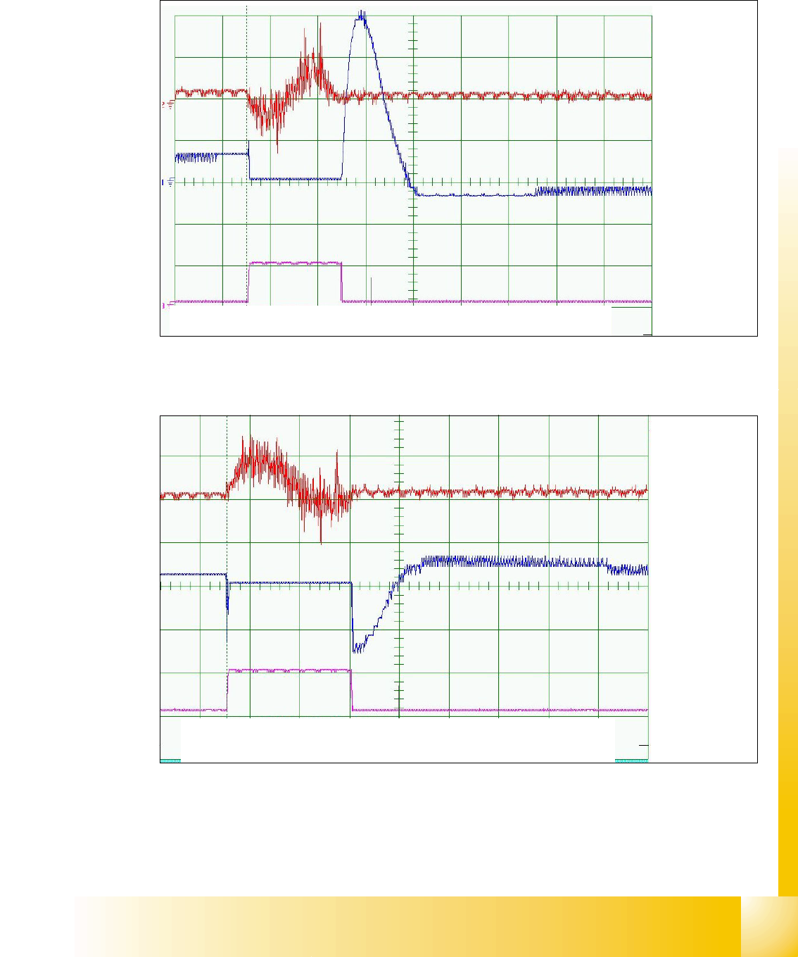
TWIN- head - View for D-Axis 90 degree
7
Fig. 7.6 - 13 Dynamic signals D-axis 90 degree rotation
TWIN- head - View for D-Axis 180 degree
Fig. 7.6 - 14 Dynamic signals D-axis 180 degree rotation
Positioning time:approx. 150ms +/- 20ms, Distance 90000 digits
Current nominal
Deviation of pos.
End signal
200mV/Div
500mV/Div
50ms/Div
5V/Div
Positioning time: approx.190ms +/- 20ms Distance180000 digits
Current nominal
Deviation of pos.
End signal
200mV/Div
500mV/Div
50ms/Div
5V/Div


Student Guide SIPLACE X
Edition 09/2005 Contents
1
Chapter
Table of Contents
8 Collect&Place-Head 20 . . . . . . . . . . . . . . . . . . . . . . . . . . . . . . . . . . . . . . . . . . . . . . . 3
8.1 Overview . . . . . . . . . . . . . . . . . . . . . . . . . . . . . . . . . . . . . . . . . . . . . . . . . . . . . . . . . . . . . . . . . . . . . . . 3
8.1.1 Technical Data C&P 20 Head. . . . . . . . . . . . . . . . . . . . . . . . . . . . . . . . . . . . . . . . . . . 4
8.1.2 Function principle C&P 20 Head . . . . . . . . . . . . . . . . . . . . . . . . . . . . . . . . . . . . . . . . . 5
8.1.3 Parts overview with describtion . . . . . . . . . . . . . . . . . . . . . . . . . . . . . . . . . . . . . . . . . . 6
8.1.3.1 Vacuum generator . . . . . . . . . . . . . . . . . . . . . . . . . . . . . . . . . . . . . . . . . . . . . . . . 7
8.1.3.2 Z-Drive . . . . . . . . . . . . . . . . . . . . . . . . . . . . . . . . . . . . . . . . . . . . . . . . . . . . . . . . . 8
8.1.3.3 Retract unit . . . . . . . . . . . . . . . . . . . . . . . . . . . . . . . . . . . . . . . . . . . . . . . . . . . . . . 9
8.1.3.4 Component Sensor . . . . . . . . . . . . . . . . . . . . . . . . . . . . . . . . . . . . . . . . . . . . . . . 9
8.1.3.5 Star. . . . . . . . . . . . . . . . . . . . . . . . . . . . . . . . . . . . . . . . . . . . . . . . . . . . . . . . . . . 11
8.1.3.6 DP-Drive. . . . . . . . . . . . . . . . . . . . . . . . . . . . . . . . . . . . . . . . . . . . . . . . . . . . . . . 12
8.1.3.7 Star Drive . . . . . . . . . . . . . . . . . . . . . . . . . . . . . . . . . . . . . . . . . . . . . . . . . . . . . . 13
8.1.3.8 Component camera . . . . . . . . . . . . . . . . . . . . . . . . . . . . . . . . . . . . . . . . . . . . . . 14
8.1.3.9 Nozzle Changer . . . . . . . . . . . . . . . . . . . . . . . . . . . . . . . . . . . . . . . . . . . . . . . . . 14
8.1.4 Pressure air supply DLM 2 C&P head. . . . . . . . . . . . . . . . . . . . . . . . . . . . . . . . . . . . 15
8.1.4.1 Holding circuit. . . . . . . . . . . . . . . . . . . . . . . . . . . . . . . . . . . . . . . . . . . . . . . . . . . 15
8.1.4.2 Overview Air kiss supply. . . . . . . . . . . . . . . . . . . . . . . . . . . . . . . . . . . . . . . . . . . 16
8.1.4.3 Overview Vacumm supply . . . . . . . . . . . . . . . . . . . . . . . . . . . . . . . . . . . . . . . . . 17
8.2 Reference Run . . . . . . . . . . . . . . . . . . . . . . . . . . . . . . . . . . . . . . . . . . . . . . . . . . . . . . . . . . . . . . . . . 19
8.2.1 Reference Run for C&P20 Head . . . . . . . . . . . . . . . . . . . . . . . . . . . . . . . . . . . . . . . . 20
8.2.2 Preparing the Z-axis Reference Run . . . . . . . . . . . . . . . . . . . . . . . . . . . . . . . . . . . . . 21
8.2.3 Star Axis Reference Run . . . . . . . . . . . . . . . . . . . . . . . . . . . . . . . . . . . . . . . . . . . . . . 21
8.2.4 Z-Axis Reference Run . . . . . . . . . . . . . . . . . . . . . . . . . . . . . . . . . . . . . . . . . . . . . . . . 22
8.2.5 DP Axis Reference Run. . . . . . . . . . . . . . . . . . . . . . . . . . . . . . . . . . . . . . . . . . . . . . . 23
8.2.6 Vacuum Check Procedure. . . . . . . . . . . . . . . . . . . . . . . . . . . . . . . . . . . . . . . . . . . . . 24
8.2.7 Determining the Vacuum and Threshold Values . . . . . . . . . . . . . . . . . . . . . . . . . . . . 25
8.2.8 Measuring Z- axis position for Component Recognition by the Component Sensor. 26
8.2.9 Height reference run . . . . . . . . . . . . . . . . . . . . . . . . . . . . . . . . . . . . . . . . . . . . . . . . . 27
8.2.10 Sequence of height reference run . . . . . . . . . . . . . . . . . . . . . . . . . . . . . . . . . . . . . . 28
8.3 Pickup and Placement Cycle for Collect & Place Head 20. . . . . . . . . . . . . . . . . . . . . . . . . . . . . . 29
8.3.1 Working Positions at the Placement Head . . . . . . . . . . . . . . . . . . . . . . . . . . . . . . . . 29
8.3.2 20 Nozzle Collect & Place Head in Home Position 0° . . . . . . . . . . . . . . . . . . . . . . . . 30
8.3.3 PCB position recognition and temperature compensation . . . . . . . . . . . . . . . . . . . . 30
8.3.4 PCB Position Recognition - Centering of the PCB Fiducials . . . . . . . . . . . . . . . . . . . 31
8.3.5 Turning Nozzles 1 to 20 to the Pickup Angle (0° or 90°) . . . . . . . . . . . . . . . . . . . . . . 32
8.3.6 Check Nozzle Length for Component Recognition . . . . . . . . . . . . . . . . . . . . . . . . . . 32
8.3.7 Picking Up the First Component . . . . . . . . . . . . . . . . . . . . . . . . . . . . . . . . . . . . . . . . 33
8.3.8 Picking Up the 10th Component . . . . . . . . . . . . . . . . . . . . . . . . . . . . . . . . . . . . . . . . 33