SiplaceX4_en.pdf - 第37页
1 - 13 S tudent Guide SIPLACE X Edition 09/2005 2 Overview 13 2.2.2.1 Pneumatic Circuit for Cooling the Y - Linear Motor for Placeme nt Area 1/2 An additional pneumatic system, supplied by ambient air , has been develope…

1 - 12
Student Guide SIPLACE X
2 Overview Edition 09/2005
12
2.2.2 Pneumatic unit
The pneumatic unit is mounted on a compact rack unit and located on the right side of the middle
section. A lockable door, which can be opened with the machine key, prevents access to the unit.
The pneumatic unit contains all electrical connections for the compressed air and transport control
systems. The transport control system with the SMEMA (Siemens) board interface facilitates the
transport of PCBs within the machine and to the previous/next stations.
Fig. 2.2 - 3 Pneumatic unit as rack unit
(1) Manual main shut-off valve
(2) Manometer for machine components
(3) Manometer for compressed air into the gantry distributor (0 - 0.6 MPa, 0 - 6 bar)
(4) Manometer for bulkcase feeder and nozzle changer
(5) Main input manometer
(6) Filter compressed air
(7) Screw, for opening and pulling out the pneumatic unit
(8) Transport control with connections to previous and next stations
8

1 - 13
Student Guide SIPLACE X
Edition 09/2005 2 Overview
13
2.2.2.1 Pneumatic Circuit for Cooling the Y - Linear Motor for Placement Area 1/2
An additional pneumatic system, supplied by ambient air, has been developed to cool the Y-mo-
tors. The ambient air is sucked in over a filter with the aid of a fan motor and supplied to the Y-
motors. The compressed air then escapes at the side of the Y-motor.
2.2.2.2 Pneumatic Circuit for Cooling the X - Linear Motor for Placement Area 1/2
The X-motors are cooled with exhaust air from the vacuum generator of the C&P head or twin
head.
2.2.2.3 Compressed Air Distributor Block
The pneumatic unit is used to prepare and distribute the compressed air required in the machine.
The pressure in the compressed air connection have to 5.0 bar.
The following pneumatic circuits are supported via the compressed air distributor block:
– Gantries 1-4 (placement heads), vacuum generation: 5.0 bar
– Transport system: 5.0 bar
– Tape cutter for the locations 1-4: 5.0 bar
– Nozzle changer for the locations 1-4: 5.0 bar
– Docking units for the component changeover table: 5.0 bar
– Bulkase feeder on the location 1-4: 2.5 bar
The fine adjustment of the individual pneumatic circuits is performed via throttle valves at the
pneumatic units.
WARNING: Tthe nozzle changer for the C&P20 head is operated with 4.5 bar, in contrast to the
nozzle changers for C&P6/12 heads, which use 2.5 bar.
1 - 14
Student Guide SIPLACE X
2 Overview Edition 09/2005
14
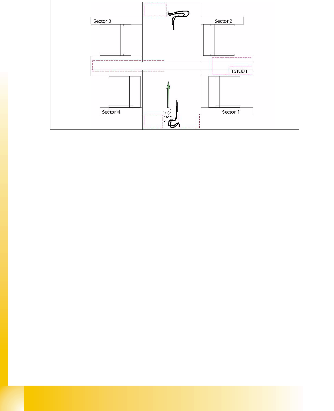
2.2.3 Sectors 1 - 4
Fig. 2.2 - 4 Overview of sectors 1-4
Sector 1/3: 2
– Connector modules for safety circuit and Start/Stop switch
– Boards for single-handed operation of component tables at location 1/4 or sector 3 for location
3/2.
– Signalling circuits for the covers
Sector 2 (main distributor): 2
– CAN I/O module with 1-wire module
– Vision illumination control board for IC camera and/or FC camera (optional)
– DC/DC converter IC camera and FC camera (Illumination)
– Main distributor (connector modules)
– Terminals X1qa (GND,+5V,+15V,-15V,+24V,.Start/Stop-signal, covers, emergency stop signal,
SW enabling signal)
– Connector modules for safety circuit and Start/Stop switch
Sector 4 (subdistributor): 2
– CAN I/O module with 1-wire module
– Vision illumination distribution board for twin head IC camera or FC camera (optional)
– DC distributor IC camera and FC camera (Illumination) in placement area 1, if installed.
– Subdistributor (connector modules)
– Terminals X1ra (GND,+5V,+15V,-15V,+24V,Start/Stop-signal, covers, E-stop signal,...)
– Connector modules for safety circuit and Start/Stop switch
Axis unit PA 2
Axis unit PA 1 HF3