SiplaceX4_en.pdf - 第370页
1 - 4 S tudent Guide SIPLACE X 8 Collect&Place-Head 20 Edition 09/2005 4 8.1.1 T echnical Dat a C&P 20 Head PLEASE NOTE: Head modularity After exchange the head the axes dynamic will be ad just automatically from…
1 - 3
Student Guide SIPLACE X
Edition 09/2005 8 Collect&Place-Head 20
3
8 Collect&Place-Head 20
8.1 Overview
The Siplace X machine have, depending on your configuration, max. 4 C&P 20 heads on a X4,
with a X3 max. 2 C&P 20 heads and one C&P 20 head on the X2 machine (see chapter overview).
8
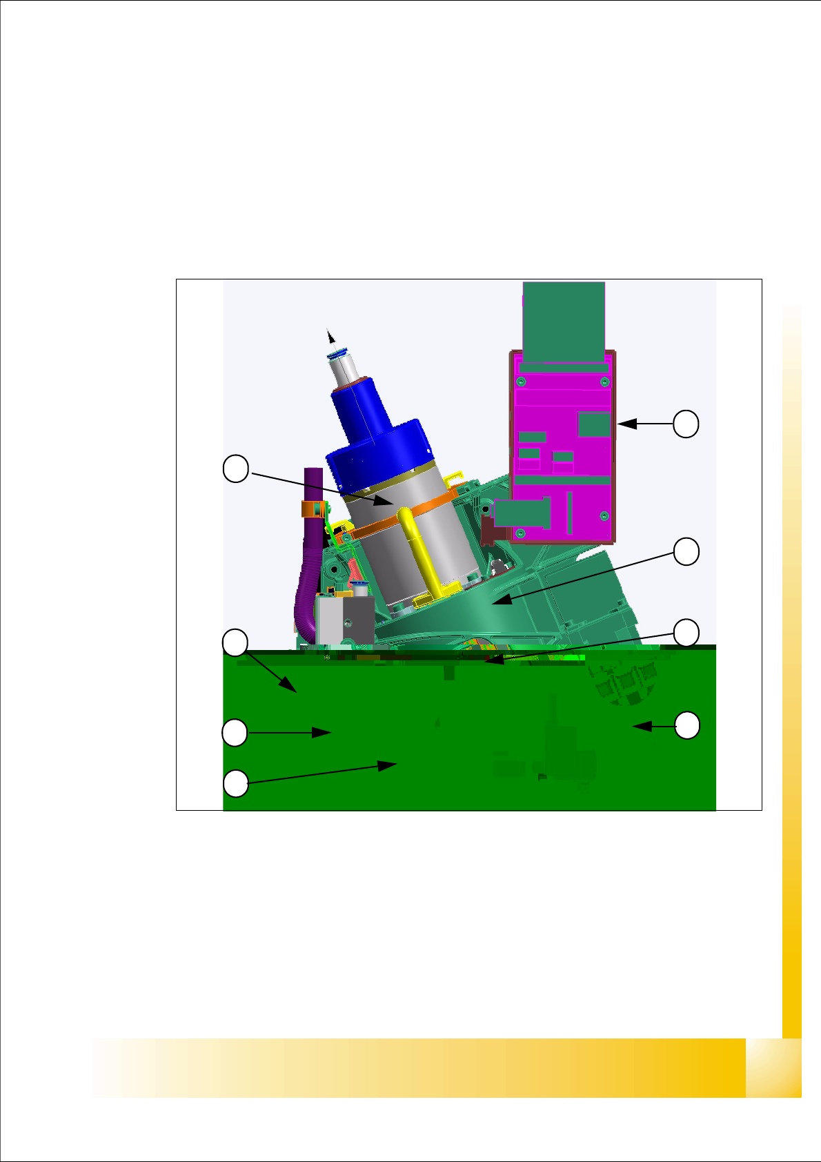
Fig. 8.1 - 1 Collect&Place20 Head- Overview
Legend
(1) Head Housing (2) Star, mounted with 20 DP-Drives
(3) Component camera (4) Intermediate distributor
(5) Component -sensor (6) Vacuum generator (digital)
(7) Z-Axis with incremental encoder (8) Star motor with incremental encoder
1
6
5
4
3
2
7
8
1 - 4
Student Guide SIPLACE X
8 Collect&Place-Head 20 Edition 09/2005
4
8.1.1 Technical Data C&P 20 Head
PLEASE NOTE: Head modularity
After exchange the head the axes dynamic will be adjust automatically from the axes data base
at the configuration setting.
.
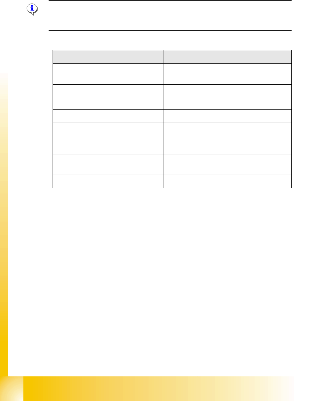
Description C&P20- head
Component size
01005 up to 2220, Melfs, Bare Dies, Flip Chip´s,
SOT, SOD, BE´s up to max. 6x6mm
Component height 4,0 mm
Component weight max. 1g
Placement Accuracy
+/- 55µm at 4 (Sigma)
Angle Accuracy
+/- 0,8° at 4 (Sigma)
Placement force
2,0N +/- 0,5N
3,5N and 4,5N +/- 1N
Nozzle types
1001, 1003, 1004, 1006, 1011, 1032-1037
1235 for calibration tool of the C&P 20 head
Nozzle changer
set up for each 6 magazine with 12 garage,
Table 8.1 - 1 Technical data 20 Segment C&P head

1 - 5
Student Guide SIPLACE X
Edition 09/2005 8 Collect&Place-Head 20
5
8.1.2 Function principle C&P 20 Head
C&P20 Head Functions
C&P20 head work according to the collect & place principle, as do C&P12 heads.
While the Star revolves, the components can be rotated into the required centering position. After
optical measurement, the components are again rotated into the correct placement positions,
while the star is revolving. The Star axis stops when placement is performed.
This means that each segment is equipped with its own DP drive, to allow angle adjustment while
the star is revolving. Each DP drive has its own control board and vacuum generator.
Communication to the 20 DP drives is via a head CAN bus with collector ring. This makes conti-
nuous star rotation possible.
In the pickup and placement position the Z-axis moves the complete DP drive unit upwards and
downwards.
Compressed air is supplied to the 20 Venturi nozzles in the holding circuit via the hollow designed
shaft of the Star motor.
A vacuum generator in the pickup/placement circuit is used to increase the vacuum during pickup
and apply air kiss to eliminate the holding circuit vacuum and release the component, during
placement.
In the pickup/placement position, the standard component sensor is used to check the presence
or height of components on the nozzle, both before and after pickup/placement.
Advantages compared with DLM Heads:
The holding circuit has one Venturi nozzle for each segment tis lead to: No more interference bet-
ween segments.
No valve plunger anymore but a digital vacuum generator (for faster switching times between va-
cuum and air kiss).
The placement star is now positioned at an angle this lead to a compact space for arranging the
20 segments and integrating the component camera into the head.
Lower inlet pressure lead to reduced air consumption per segment.
Autonomous revolution and positioning of each segment increases placement capacity.
No swiveling in and out of DP station onto the segment this guarantee a better accuracy and ro-
bustness.
Component sensor in the pickup/placement position this lead to higher placement reliability.
Digital camera interface This lead to faster image evaluation
Linear motor with Z drive : reduction of moving mass this increases placement capacity.