SiplaceX4_en.pdf - 第372页
1 - 6 S tudent Guide SIPLACE X 8 Collect&Place-Head 20 Edition 09/2005 6 8.1.3 Part s overview with describtion The following chapter described the main part s of the C&P20 Head and their technical function. The …

1 - 5
Student Guide SIPLACE X
Edition 09/2005 8 Collect&Place-Head 20
5
8.1.2 Function principle C&P 20 Head
C&P20 Head Functions
C&P20 head work according to the collect & place principle, as do C&P12 heads.
While the Star revolves, the components can be rotated into the required centering position. After
optical measurement, the components are again rotated into the correct placement positions,
while the star is revolving. The Star axis stops when placement is performed.
This means that each segment is equipped with its own DP drive, to allow angle adjustment while
the star is revolving. Each DP drive has its own control board and vacuum generator.
Communication to the 20 DP drives is via a head CAN bus with collector ring. This makes conti-
nuous star rotation possible.
In the pickup and placement position the Z-axis moves the complete DP drive unit upwards and
downwards.
Compressed air is supplied to the 20 Venturi nozzles in the holding circuit via the hollow designed
shaft of the Star motor.
A vacuum generator in the pickup/placement circuit is used to increase the vacuum during pickup
and apply air kiss to eliminate the holding circuit vacuum and release the component, during
placement.
In the pickup/placement position, the standard component sensor is used to check the presence
or height of components on the nozzle, both before and after pickup/placement.
Advantages compared with DLM Heads:
The holding circuit has one Venturi nozzle for each segment tis lead to: No more interference bet-
ween segments.
No valve plunger anymore but a digital vacuum generator (for faster switching times between va-
cuum and air kiss).
The placement star is now positioned at an angle this lead to a compact space for arranging the
20 segments and integrating the component camera into the head.
Lower inlet pressure lead to reduced air consumption per segment.
Autonomous revolution and positioning of each segment increases placement capacity.
No swiveling in and out of DP station onto the segment this guarantee a better accuracy and ro-
bustness.
Component sensor in the pickup/placement position this lead to higher placement reliability.
Digital camera interface This lead to faster image evaluation
Linear motor with Z drive : reduction of moving mass this increases placement capacity.
1 - 6
Student Guide SIPLACE X
8 Collect&Place-Head 20 Edition 09/2005
6
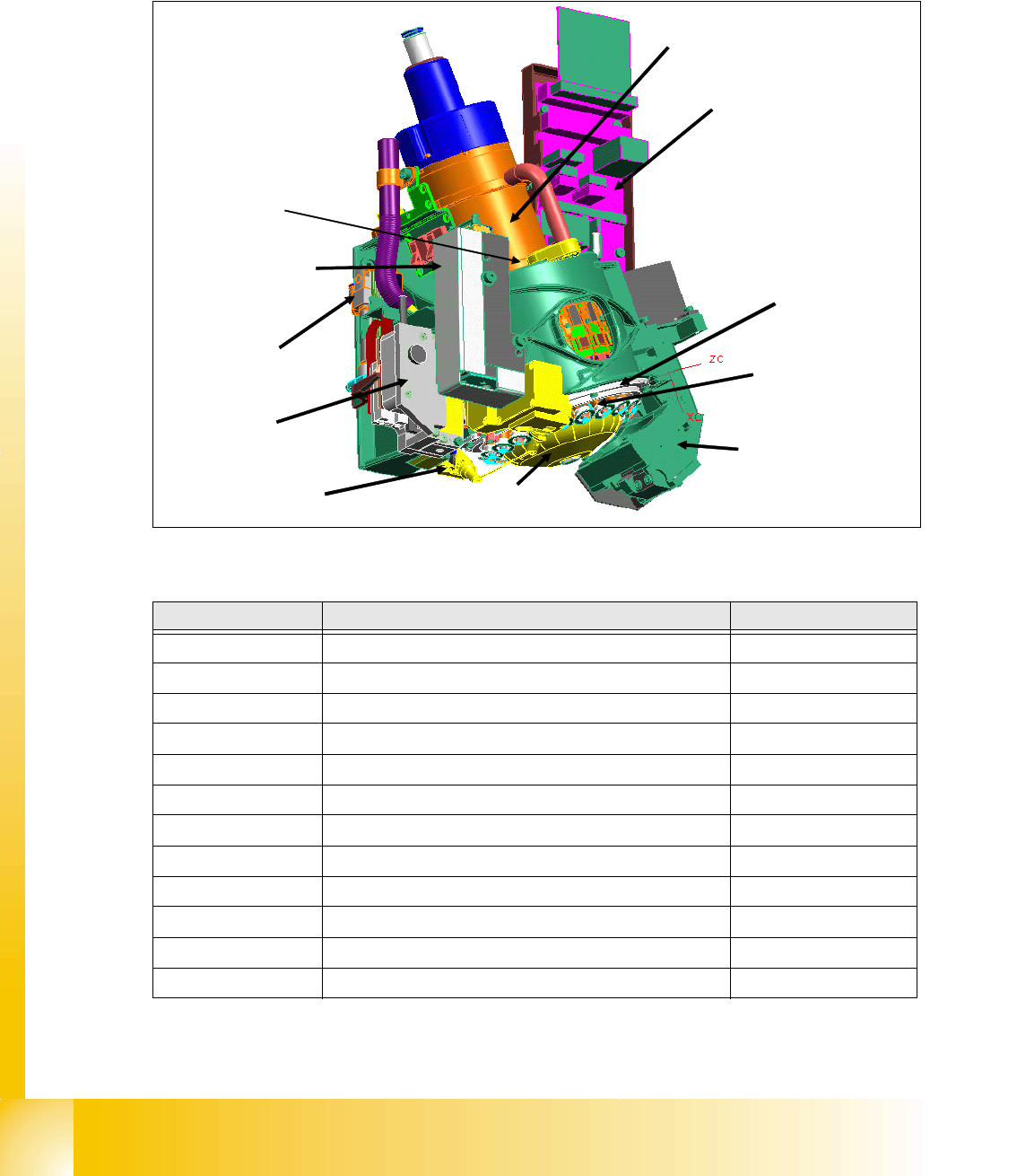
8.1.3 Parts overview with describtion
The following chapter described the main parts of the C&P20 Head and their technical function.
The sequence of the description is the sequence of disasemble for service.
8
Fig. 8.1 - 2 C&P20 Head- Parts overview
8
Position in Description Rart-Nr.
1
Collect&Place 20-Head 03008827-0X
2
E/D transmitter 03007834-0X
3
Vacuum generator (Placement/Pick up circuit) 03005070-0X
4
Retract unit 03007696-0X
5
Z-Drive 03005155-0X
6
Component -Sensor 03006742-0X
7
Star motor 03005097-0X
8
Intermediate distributor 03005158-0X
9
Raceway 03013243-0X
10
DP- Drive 03005109-0X
11
Component Camera 03003426-0X
12
Silencer holding circuit 03005121-0X
Table 8.1 - 2 Parts overview C&P 20
(7)
(6)
(11)
(3)
(5)
(10)
(9)
(2)
(12)
(4)
(8)
1 - 7
Student Guide SIPLACE X
Edition 09/2005 8 Collect&Place-Head 20
7
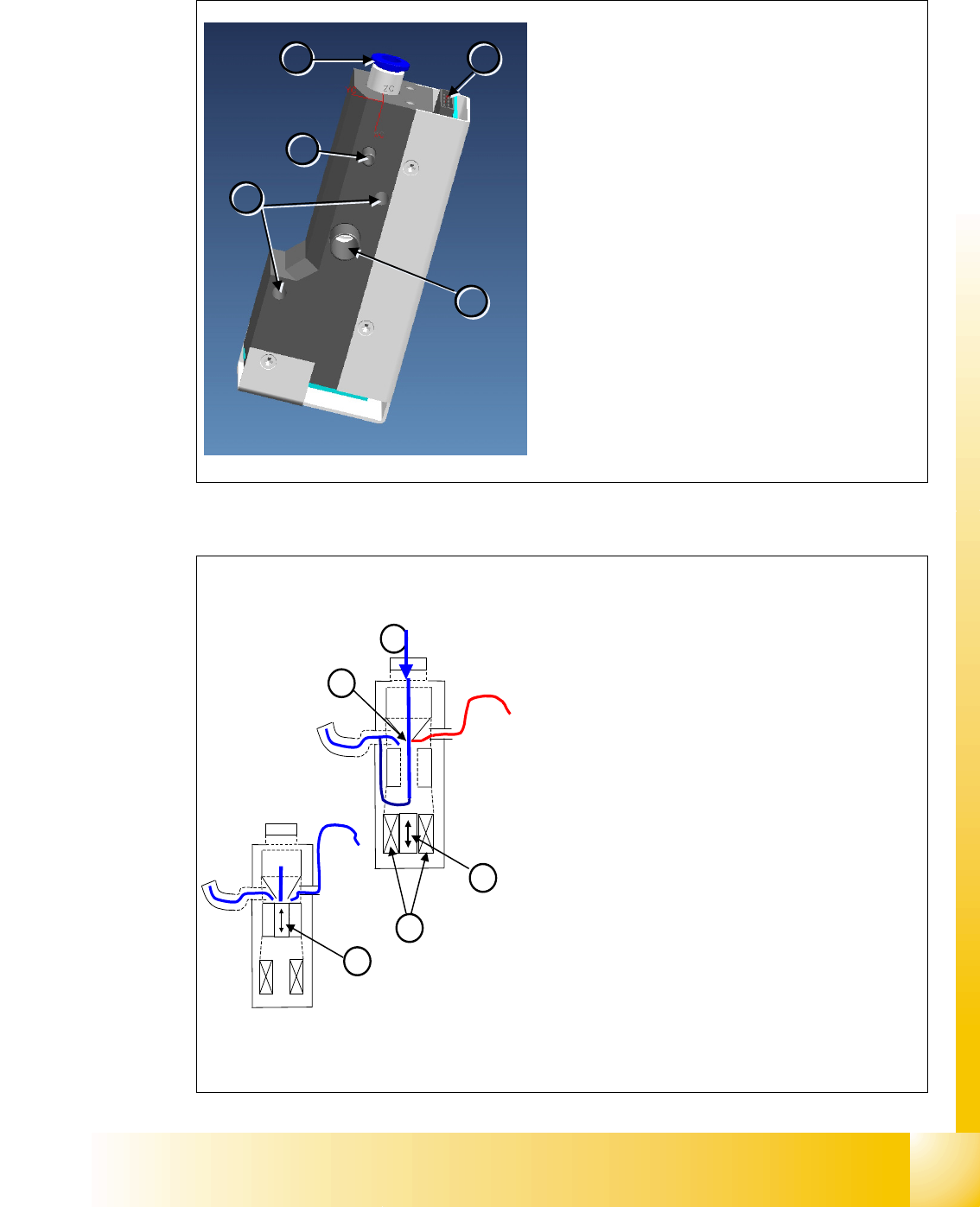
8.1.3.1 Vacuum generator
1
1
2
2
3
3
4
4
5
5
Vacuum generator (digital)
– The pressure control valve supplies the pickup
/
placement circuit with vacuum during the pickup
process and switches over to air kiss during
placement.
– This valve is fixed to the placement head with
two screws and can be replaced during service
work.
Vacuum generator Details
– Compressed air connection (1)
– Vacuum/air kiss (2) for pickup/placement circuit
– Discharged air
(3), for cooling the X linear motor
– Energy and data supply
(4)
– Mounting (5) for vacuum generator
4
2
1
3
2
Vacuum generator - Function
– After initialization, the piston is in a “central posi-
tion”, in which neither vacuum nor air kiss is ap-
plied to the nozzle.
– During pickup, the piston is always in the ‘open’
position, in which maximum vacuum is produced
and applied to the nozzle.
– The function “early vacuum” should always be
switched on for the C&P20 head.However, if this
function is switched off, the piston will start off by
being in the ‘open’ position and will then return to
the “central position” . The vacuum will only be
switched on again after the "light barrier down"
signal has been issued . -> 2 additional switching
steps -> time loss.
Vacuum generator Details
– Compressed air (1)
– Piston (2)
– Motor (3)
– Venturi nozzle (4)