SiplaceX4_en.pdf - 第375页
1 - 9 S tudent Guide SIPLACE X Edition 09/2005 8 Collect&Place-Head 20 9 8.1.3.3 Retract unit Retract Unit Functions – At zero current, the bear ing friction of the Z-axis is not sufficient to protect the axis from f…
1 - 8
Student Guide SIPLACE X
8 Collect&Place-Head 20 Edition 09/2005
8
8.1.3.2 Z-Drive
Description Part No:
Z-Drive
03005155-0X
Z-Motor
03005183-0X
Light barrier "Z- Axis bottom"
03007833-0X
1
1
4
4
3
3
2
2
5
5
5
5
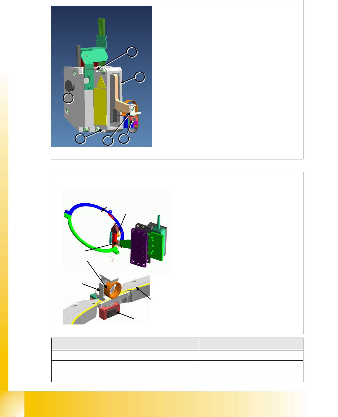
Z-Axis
– The Z-axis and retract unit are fixed to the head as a
complete unit, with two screws, and can be easily re-
placed during service work.
Z-Axis Unit Details
– Incremental measurement system (1) resolution
0,5µm.
– Linear motor, primary part
(2) moves between the
secondary parts up and down.
– Light barrier Z-down
(3) emits the end position sig-
nal for the Z-axis.
–Jaw
(4). The ball bearing for the DP drive is rotated
via the star axis into the jaw, allowing the segment to
be moved upwards and downwards.
– Mounting
(5) for Z-axis
Segment
ball bearings
Segment
Raceway
Jaw
Raceway
Light barrier
Z-down
Z-Drive - Function
– The jaws are installed on the primary part of
the Z-motor, for mechanical docking of the
segments.
– A Z-bottom sensor is located in the place-
ment position, for recognition of the Z-axis
put-on position. This recognizes a relative
movement between the nozzle and DP seg-
ment. When the Z-axis springs into place, this
sensor sends a signal to the axis card.The
"light barrier down" signal is directly linked to
the measurement signal of the Z-axis incre-
mental encoder.
1 - 9
Student Guide SIPLACE X
Edition 09/2005 8 Collect&Place-Head 20
9
8.1.3.3 Retract unit
Retract Unit Functions
– At zero current, the bearing friction of the Z-axis is not sufficient to protect the axis from falling
down. A pneumatic retract system has been installed to protect the Z-axis should the gantry
be moved when the machine is switched off. This retract unit keeps the Z-axis in the safe, up-
per position during zero current.
Please Note: 8
The Z-axis control system is designed to ensure that, should the machine power supply fail (or be
switched off), there is always enough power temporarily stored by the Z-motor servo unit and axis
card to move the Z-axis to the upper position.
Power failure is recognized by the issuance of a „Power fail“ signal. This „Power fail“ signal
enables the relevant function (upwards movement and activation of the retract unit) on the axis
controller.
8.1.3.4 Component Sensor
The component sensor is no longer a option like the 6/12 C&P head. Also the function and position
of the component sensor is different. The component sensor is mounted directly in the placement
and pick up position, so that we recognize the component after pick up and before placement. The
Z-Axis moves downwards and upwards trough the Laser beam.
When the Laser beam is interrupted or relaesed the exactly Z-position is recording by the axis
card. So we determined in each situation if a component on the nozzle or not.
(Before Pick up: No Component on the nozzle, After Pick up: Component on the nozzle; Before
Placement: Component still on the nozzle, After placement: No Component on the nozzle)
5
4
3
2
1
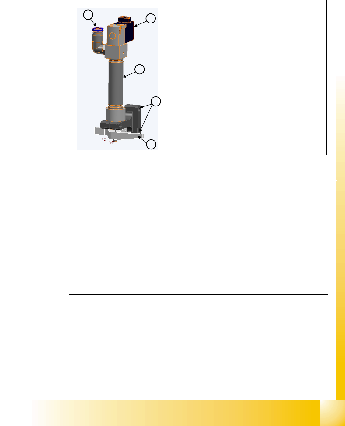
Retract unit
The retract unit is installed on the Z-axis and is respon-
sible for protecting the Z-axis from damage, by moving
it into a safe area in the case of unexpected events e.g.
power cuts or machine shutdown.
The retract unit is fixed with two screws and can be eas-
ily replaced during service work.
Retract unit Details
Pneumatic cylinder (1)
Solenoid valve (2)
Compressed air connection (3)
Mounting of retract unit (4)
Z-axis driver (5)
1 - 10
Student Guide SIPLACE X
8 Collect&Place-Head 20 Edition 09/2005
10
Pickup Process:
– When the Z-axis moves downwards, the nozzle interrupts the Laser beam.At this exact mo-
ment, the Z-axis position is recorded and compared to the reference value, to see whether
there is still a component on the nozzle. If the Z-axis position indicates that there is a compo-
nent on the nozzle, the Z-axis will be immediately stopped. An error message will be issued
or the component will be rejected.
– When the Z-axis moves upwards again, the Laser beam is released and the Z-position re-
corded. Based on the Z-position during downwards movement, the system can now determine
the presence and height of a component.
Placement Process:
– During the placement process, the system checks whether the component is at the nozzle/
whether placement has been performed on the component.
1
3
2
4
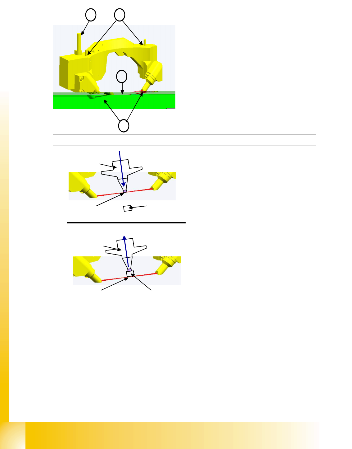
Component Sensor
– In its standard state, the component sensor is
installed in the pickup-placement position on
the C&P20 head.
– The sensor is fixed to the head with two
screws and can be replaced as a complete
unit during service work.
Component Sensor Details
– Power/data supply cable (1)
– Transmitter and receiver unit (2)
– LASER beam
(3)
– Mounting (4) to housing
Component
Nozzle
Recording of Z-
position when the
LASER beam is
interrupted
Downwards movement
Component
Nozzle
Upwards movement
Recording of Z-position
when the LASER beam is
free again
Component Sensor Functions
– The component sensor determines the com-
ponent and nozzle height during the place-
ment process.
– The component sensor signal is directly
linked to the measurement signal of the Z-
axis incremental encoder.