SiplaceX4_en.pdf - 第382页
1 - 16 S tudent Guide SIPLACE X 8 Collect&Place-Head 20 Edition 09/2005 16 8.1.4.2 Overview Air kiss supply Red (light grey): V acuum Blue (black): pressure air (Air kiss) 8 Fig. 8.1 - 4 General overvi ew ot th e fun…
1 - 15
Student Guide SIPLACE X
Edition 09/2005 8 Collect&Place-Head 20
15
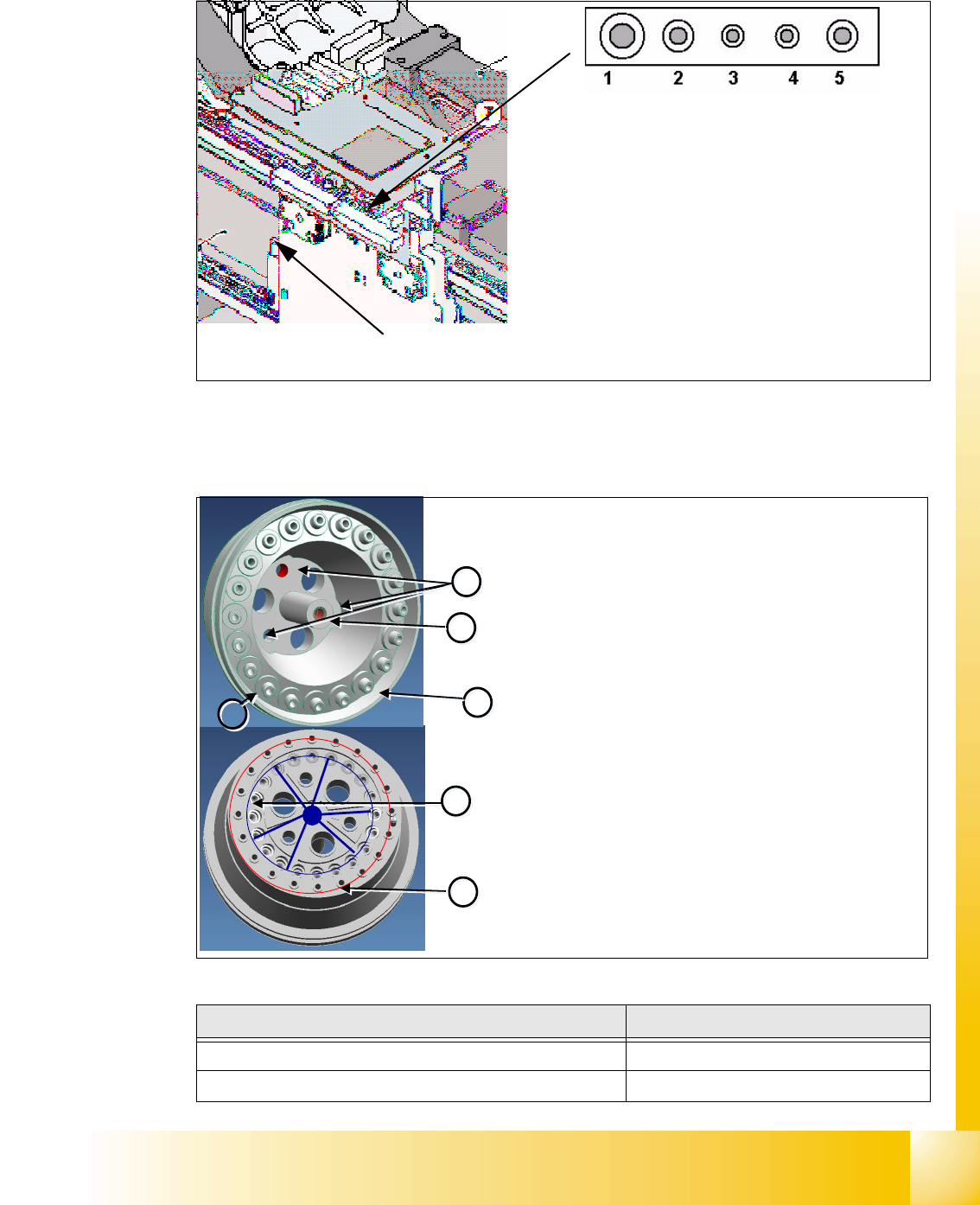
8.1.4 Pressure air supply DLM 2 C&P head
Fig. 8.1 - 3 Pressure air connectors C&P head
8.1.4.1 Holding circuit
(1) Pressure air connector for C&P-head Va-
cuum-holding circuit 4,7 bar Input pressure air
for the Placement head
(2) Pressure air connector for C&P-head Va-
cuum-pick up circuit with branching for the air
kiss supply 4,7 bar Input pressure air for the
Placement head
(3)-(5) Blind connector (Connector for Twin head)
Pressure air connector for cooling
X-Motor
Description Part No.
Venturi Block
-0X
O-Ring (6)
03011347-0X
1
1
2
2
3
3
4
4
6
6
5
5
Venturi Block
The venturi block consists of 20 small venturi nozzles
and is located behind the silencer.
Each venturi nozzle supplies one segment with vacuum
in the hold circuit.
If a segment is in the pickup/placement circuit, the hold
circuit vacuum is increased (for pickup) or eliminated
via air kiss (for placement).
Venturi Block Details
– Mounting (1) for star frame
– Mounting
(2) for silencer
– Venturi nozzle discharged air
(3) to the silencer
– Venturi nozzle vacuum outlet
(4) to the segments.
– Compressed air inlet
(5) to venturi nozzle The venturi
nozzle entrances have seals.
–O-ring
(6) between venturi block and silencer
1 - 16
Student Guide SIPLACE X
8 Collect&Place-Head 20 Edition 09/2005
16
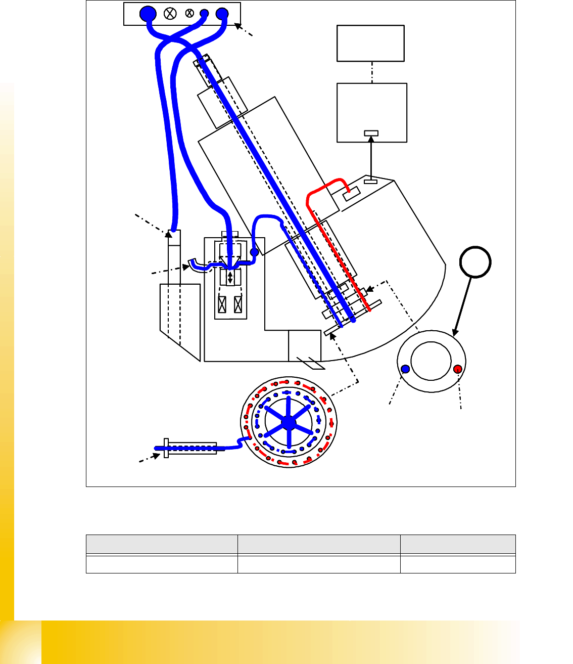
8.1.4.2 Overview Air kiss supply
Red (light grey): Vacuum
Blue (black): pressure air (Air kiss)
8
Fig. 8.1 - 4 General overview ot the function Air kiss
Position Description Part No.
1 Distributor disc
03008286-0X
Holding
circuit
Intermediate
board
Z-axis
B
B
A
Compressed
air distributor
(4.8-5.0bar)
MC
C
C
A
A
e.g. Segment 1
Pickup/
placement
circuit
Measurement of
vacuum/air kiss values is
performed in the
pressure control valve
CAN bus
1
Retract unit
Z-axis
Cooling system
X-motor
Holding
circuit
Intermediate
board
Z-axis
B
B
A
Compressed
air distributor
(4.8-5.0bar)
MC
C
C
A
A
e.g. Segment 1
Pickup/
placement
circuit
Measurement of
vacuum/air kiss values is
performed in the
pressure control valve
CAN bus
11
Retract unit
Z-axis
Cooling system
X-motor
1 - 17
Student Guide SIPLACE X
Edition 09/2005 8 Collect&Place-Head 20
17
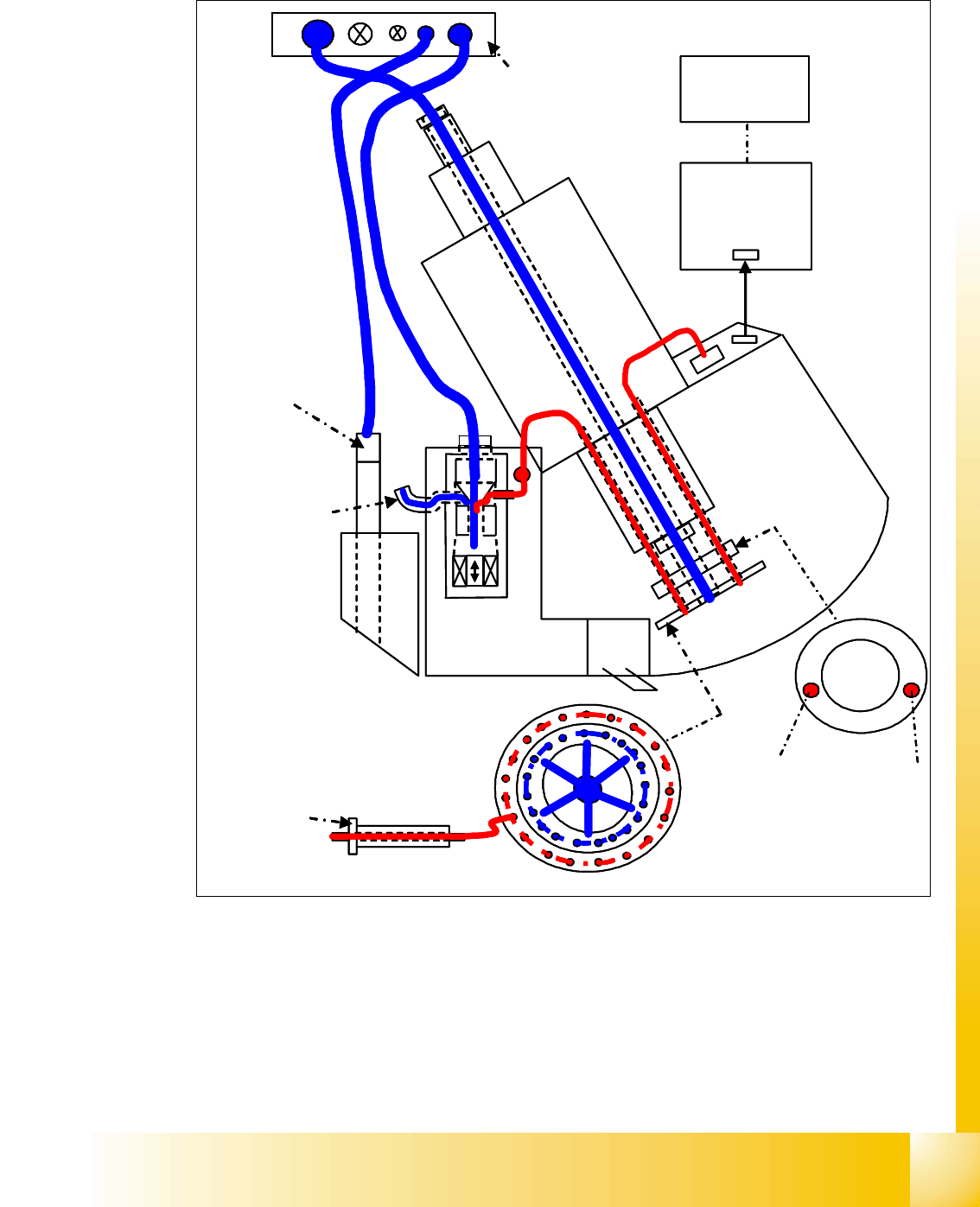
8.1.4.3 Overview Vacumm supply
8
Fig. 8.1 - 5 General overview of the function Vacuum
e.g. Segment 1
Intermediate
board
Z-axis
A
B
C
B
A
A
Compressed air
distributor
(4.8-5.0bar)
MC
CAN bus
C
Cooling system
X-motor
Retract unit
Z-axis
Pickup/
placement
circuit
A
Measurement of vacuum/
air kiss values is
performed in the
pressure control valve
e.g. Segment 1
Intermediate
board
Z-axis
A
B
C
B
A
A
Compressed air
distributor
(4.8-5.0bar)
MC
CAN bus
C
Cooling system
X-motor
Retract unit
Z-axis
Pickup/
placement
circuit
A
Measurement of vacuum/
air kiss values is
performed in the
pressure control valve