SiplaceX4_en.pdf - 第39页
1 - 15 S tudent Guide SIPLACE X Edition 09/2005 2 Overview 15 2.2.4 Computer Unit Fig. 2.2 - 5 Computer unit (1) Power su pply for D C/DC conver ter 3.3V (CPUs) (2) Power suppl y for DC/DC converter 52V / +5V 60A (3) Pow…
1 - 14
Student Guide SIPLACE X
2 Overview Edition 09/2005
14
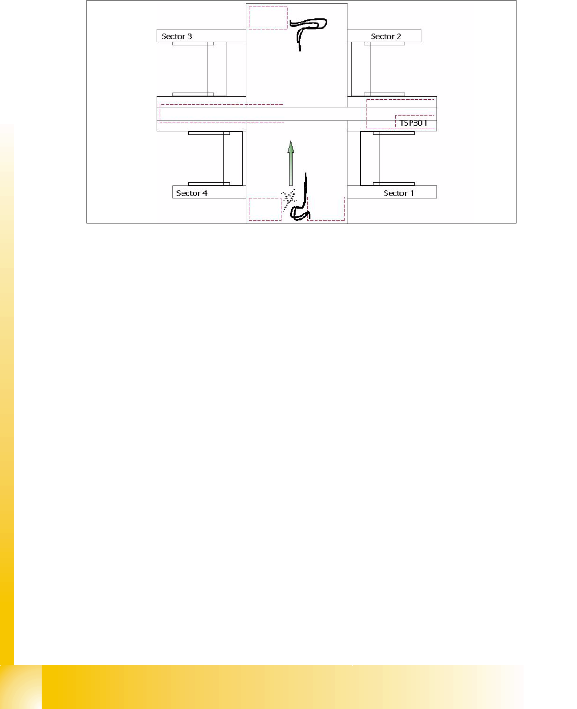
2.2.3 Sectors 1 - 4
Fig. 2.2 - 4 Overview of sectors 1-4
Sector 1/3: 2
– Connector modules for safety circuit and Start/Stop switch
– Boards for single-handed operation of component tables at location 1/4 or sector 3 for location
3/2.
– Signalling circuits for the covers
Sector 2 (main distributor): 2
– CAN I/O module with 1-wire module
– Vision illumination control board for IC camera and/or FC camera (optional)
– DC/DC converter IC camera and FC camera (Illumination)
– Main distributor (connector modules)
– Terminals X1qa (GND,+5V,+15V,-15V,+24V,.Start/Stop-signal, covers, emergency stop signal,
SW enabling signal)
– Connector modules for safety circuit and Start/Stop switch
Sector 4 (subdistributor): 2
– CAN I/O module with 1-wire module
– Vision illumination distribution board for twin head IC camera or FC camera (optional)
– DC distributor IC camera and FC camera (Illumination) in placement area 1, if installed.
– Subdistributor (connector modules)
– Terminals X1ra (GND,+5V,+15V,-15V,+24V,Start/Stop-signal, covers, E-stop signal,...)
– Connector modules for safety circuit and Start/Stop switch
Axis unit PA 2
Axis unit PA 1 HF3
1 - 15
Student Guide SIPLACE X
Edition 09/2005 2 Overview
15
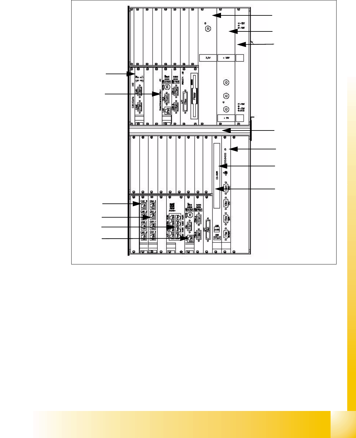
2.2.4 Computer Unit
Fig. 2.2 - 5 Computer unit
(1) Power supply for DC/DC converter 3.3V
(CPUs)
(2) Power supply for DC/DC converter 52V /
+5V 60A
(3) Power supply for DC/DC converter +/-12V
(+/-15V not used)
(4) Fan unit (blows downwards)
(5) Video multiplexer (6) CD-ROM drive with USB port
(7) COM unit 1Mbit/s, connection at top for
BB 1 / connection at bottom for BB 2
(8) CPU unit machine control (MC)
(9) Hotlink card for cameras (BB1) (10) Hotlink card for cameras (BB2)
(11) Dual LAN unit (12) CPU unit station computer (SC)
1
2
3
4
5
7
8
9
10
11
12
6
3.6V back-up battery
on the rear of the
computer unit
1 - 16
Student Guide SIPLACE X
2 Overview Edition 09/2005
16
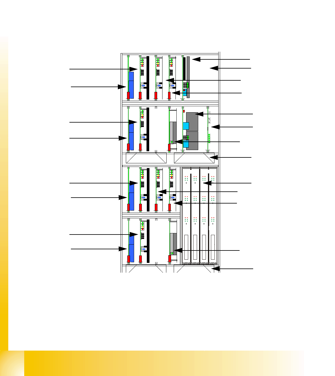
2.2.5 Axis Unit
The axis unit contains the servo boards, axis cards, power supplies (+/-15V,+5V), ballast circuit
and anti-crash board. The flexible axis (servo) unit is equipped with servo boards/axis cards ac-
cording the machine/head configuration.
Overview of axis unit
X2 machine axis unit in BB2 for gantries 1 and 3
X3 machine axis unit in BB1 for gantries 1 and 4, axis unit in BB2 for gantry 3
X4 machine axis unit in BB1 for gantries 1 and 4, axis unit in BB2 for gantries 2 and 3
2.2.5.1 Example of Axis Unit for X4/ X3 with Two C&P20 Heads in Placement Area 1
(1) Power supply +/-15V, +5V (2) Ballast circuit board, only in axis unit BB2
(3) Power supply +/-15V (4) Anti-crash board
(5) Fan unit (blows downwards)
(6) Axis cards A363
(7) Servo amplifier for X-axis (8) Servo amplifier for Y-axes
(9) Brake board for each X-axis and Y-axis
(10)
TBS 250/10X
TBS 250 /20Y
DBM/3P-06
SDS 120/2.5S1-03
5 V / 15A 15V/1,7A 15V/ 1,7A
DC/ DC Wandler Dp-Antriebe
DBM/3P-06
TBS 250/10X
TBS 250 /20Y
DBM/3P-06
SDS 120/2.5S1-03
SDS 60 2.5Z1-02
DBM/3P-06
SDS 60/2.5Z1-02
15 V / 5A 15 V / 5A
Anti crash board
DC/ DC Wandler Dp-Antriebe
X
Y
Stern
Stern
X
Y
Frei
Frei
Z
Z
Frei
Frei
Portal 1
Portal 4
1
2
3
4
5
6
7
9
8
9
7
9
8
9
Placement area 1
Gantry 1
Placement area 1
Gantry 4
5
Servo star axis
Servo Z-axis
DC/DC converter
DP drives
DC/DC converter
DP drives
Servo Z-axis
Servo star axis