SiplaceX4_en.pdf - 第394页
1 - 28 S tudent Guide SIPLACE X 8 Collect&Place-Head 20 Edition 09/2005 28 8.2.10 Sequence of he ight reference run Fig. 8.2 - 10 Flow chart height reference run Tur n the St ar-a xi s ... to S eg m en t n Vacuum m e…
1 - 27
Student Guide SIPLACE X
Edition 09/2005 8 Collect&Place-Head 20
27
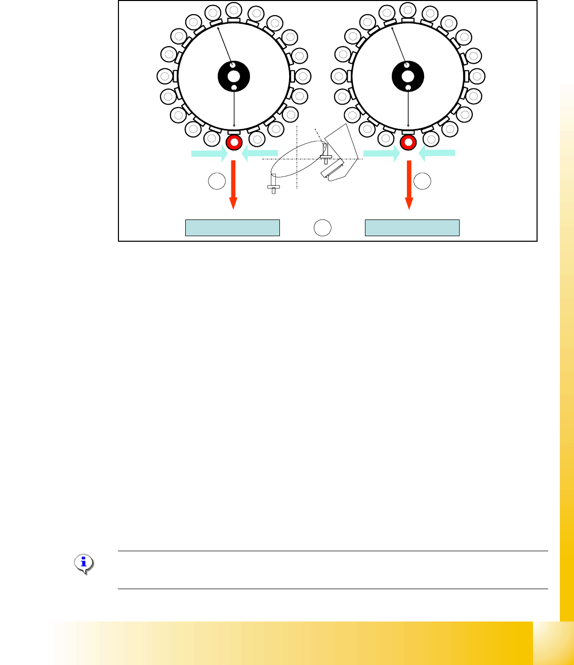
8.2.9 Height reference run
With this function we check the correct fitting of the nozzle on the sleeve and that the correct
nozzle type like the programmed one are set to the sleeves.
The nozzle length is taken to calculate the pick up and placement height for the subsequent place-
ments. !
Fig. 8.2 - 9 Measuring the nozzle height
(1) Top of the fixed conveyor side
(2) First step with segment 1 to measure the nozzle length.
(3) Last step with segment 20 to measure the nozzle length.
The gantry moves the placement head to the fixed conveyor rail at height measurement position.
The star turns the segment for measuring into the pickup/placement position
– The value "Vacuum open" is measured for each segment.
The Z-axis moves the segment downwards
– When the component sensor beam is interrupted, the Z-axis position of the component sen-
sor is determined for component sensor tasks.
When the Z -axis touches the conveyor rail, the nozzle length is determined by the Z- position
down value for nozzle length measurement.
– The closed vacuum is then determined for the accordant nozzle
The Z-axis moves upwards:
When the component sensor beam is no longer interrupted, the Z-axis position for the component
sensor will be measured again.
PLEASE NOTE: The measured length in component sensor is used for component presence or
height measurement only.
1
2
3
4
5
6
7
8
9
10
12
11
13
14
15
16
17
18
19
20
CO- Sensor
CO- Sensor
CO - Sensor
CO - Sensor
11
12
13
14
15
16
17
18
19
1
2
3
5
6
7
8
9
10
4
20
e.g. Segment 11
CO-
Camera
e.g. Segment 1
1
2
3
1 - 28
Student Guide SIPLACE X
8 Collect&Place-Head 20 Edition 09/2005
28
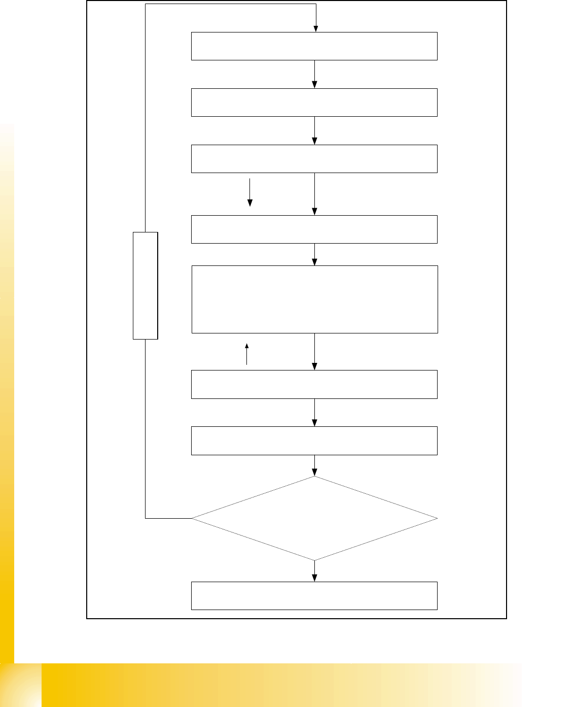
8.2.10 Sequence of height reference run
Fig. 8.2 - 10 Flow chart height reference run
Turn the Star-axis
... to Segment n
Vacuum measurment
"open"
read out Z- Position for component sensor
Z-Axis touch the Transport rail
End signal Z-Axis
--> Determine the nozzle length (with Z-pos.)
--> Determine Vacuum "closed"
read out Z-position for component sensor
End with Segment n
Z-Axis
Z-Axis
Segment n+1
Height reference run
Segment 20 ?
No
End Height
reference run
Yes
1 - 29
Student Guide SIPLACE X
Edition 09/2005 8 Collect&Place-Head 20
29
8.3 Pickup and Placement Cycle for Collect & Place
Head 20
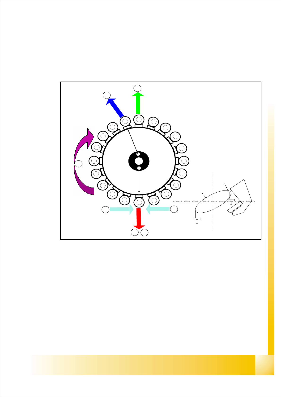
8.3.1 Working Positions at the Placement Head
Fig. 8.3 - 1 Working positions at the placement head
Key
(1) Optical centering (component camera)
(2) Vacuum measurement holding circuit
(3) Vacuum measurement placement circuit
(4) Pickup/placement station and reject position
(5) Position of component sensor
(6) Working direction
1
1
2
3
4
5
5
6
1
2
3
4
5
6
7
8
9
10
12
11
13
14
15
16
17
18
19
20
Segment 1
Segment 11
Co.-
Camera
S
t
a
r
p
o
s
i
t
i
o
n
,
6
16