SiplaceX4_en.pdf - 第397页
在线预览 SiplaceX4_en.pdf PDF 文档。
1 - 30
Student Guide SIPLACE X
8 Collect&Place-Head 20 Edition 09/2005
30
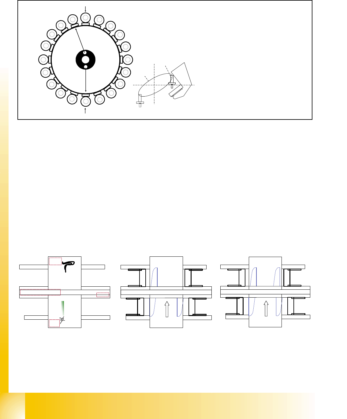
8.3.2 20 Nozzle Collect & Place Head in Home Position 0
°
Fig. 8.3 - 2 20 nozzle collect & place head in home position 0°
8.3.3 PCB position recognition and temperature compensation
The PCB recognition is necessary to determined the correct position of the PCB in the machine
(Transport --> Placement area).
It should be two fiducials on each PCB minimum. With this two fiducial we are able to determined
the X/Y position and the angle of the PCB in the transport. The fiducials shouldn‘t be in one line
on the PCB.
Up to 3 fiducials can program for the PCB recognition. With the third fiducial, we determined ad-
ditional to the position of the PCB the geometric data of the PCB layout, that means is the PCB
stretch.
The Siplace X machine increase the accuracy, so that we make additional to the PCB recognition
a temperature compensation with the second gantry in the placement area.
the
Star
axis
is
turned
to
home
position
Placement position
CO-
Camera position
1
2
3
4
5
6
7
8
9
10
12
11
13
14
15
16
17
18
19
20
Segment 1
Segment 11
S
t
a
r
p
o
s
i
t
i
o
n
CO- Camera
Star position
Digit: 10
Angle: 0°
1° is equivalent to 1000 digits
The Z-axis retract unit prevents seg-
ment 1 from falling.
TSP
30
1
Gantry 1
Gantry 3
Gantry 4
Siplace X 3
TSP
30
1
Gantry 1
Gantry 3
Gantry 4
Transport
direction
Siplace X 4
Gantry 2
1 - 32
Student Guide SIPLACE X
8 Collect&Place-Head 20 Edition 09/2005
32
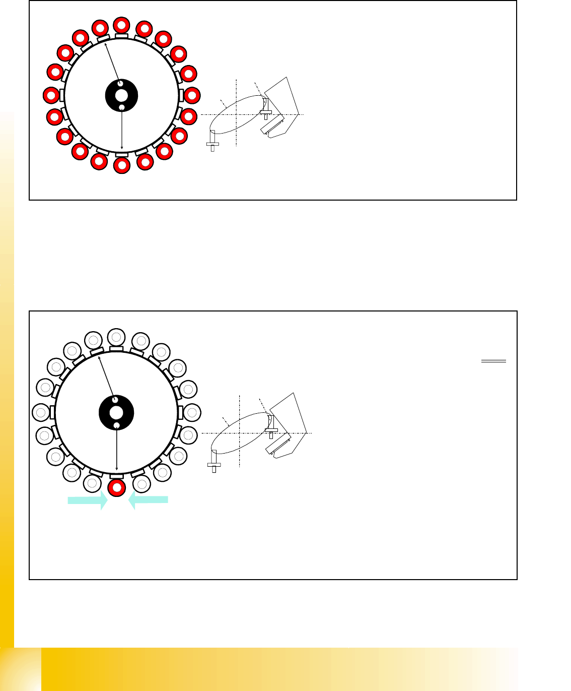
8.3.5 Turning Nozzles 1 to 20 to the Pickup Angle (0° or 90°)
Fig. 8.3 - 5 Turning segments 1 to 20 to the pickup angle (0° or 90°)
8.3.6 Check Nozzle Length for Component Recognition
Fig. 8.3 - 6 Check nozzle length "component recognition by the component sensor, before pick up"
1
2
3
4
5
6
7
8
9
10
12
11
13
14
15
16
17
18
19
20
Segment 1
Segment 11
S
t
a
r
p
o
s
i
t
i
o
n
CO- Camera
– The segments in the collect & place 20
head are turned
in succession, begin-
ning with segment 1, to the required
pickup angle of 0° or 90°.
– Note: each segment has its own DP drive
1
2
3
4
5
6
7
8
9
10
12
11
13
14
15
16
17
18
19
20
CO - Sensor
CO - Sensor
Segment 1
Segment 11
S
t
a
r
p
o
s
i
t
i
o
n
CO- Camera
Component sensor measures at star
pickup position:
– Vacuum measurement: ’Segment open’
value
–the
component sensor measures the
nozzle length. The measured length be-
fore pickup is verified with the reference
length.
– If a length difference of -0.15mm or +
0.1mm is detected, the gantry axes
move the placement head into the ser-
vice position so that the nozzle can be
replaced.
– Measurement is performed during Z-
movement in the star pickup/placement
position.