SiplaceX4_en.pdf - 第402页
1 - 36 S tudent Guide SIPLACE X 8 Collect&Place-Head 20 Edition 09/2005 36 8.3.13 Component recognition at the 1 st Segment by Component Sensor Fig. 8.3 - 13 Checking the component before placement 8.3.14 Placing the…
1 - 35
Student Guide SIPLACE X
Edition 09/2005 8 Collect&Place-Head 20
35
8.3.11 Picking Up the 13th Component
Fig. 8.3 - 11 Picking up the 13th component
The process continues with the remaining components being picked up, centred and turned to the
correct or corrected placement angle.
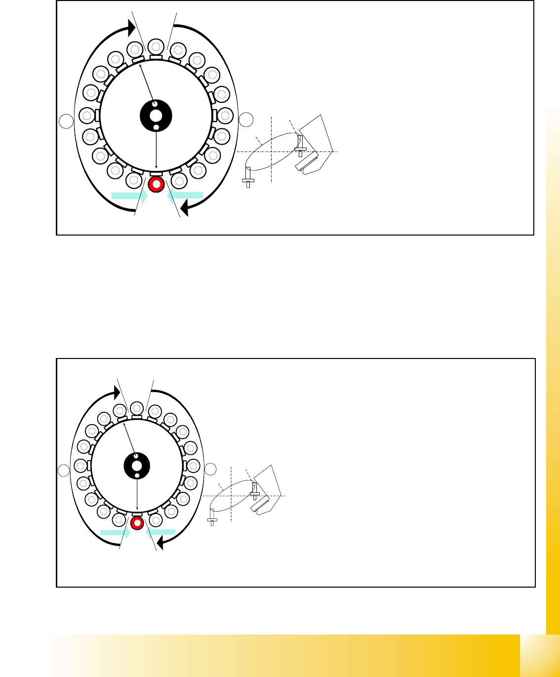
8.3.12 Picking Up the 20th Component
Fig. 8.3 - 12 Picking up the 20th component
CO - Sensor
CO - Sensor
Segment 13
Segment 3
S
t
a
r
p
o
s
i
t
i
o
n
CO-
Camera
11
12
13
14
15
16
17
18
19
1
2
3
5
6
7
8
9
10
4
20
A
B
Star position 210°
– Vision system: optical centering of the
3rd component
– Pickup/placement station:
pick up the 13th component.
–
A : The components previously picked
up are rotated to the centering angle,
here.
–
B : The components previously cen-
tered are adjusted here to their place-
ment angles.
– Measurement of hold circuit for segment
4
CO- Sensor
CO - Sensor
Segment 20
Segment 10
S
t
a
r
p
o
s
i
t
i
o
n
CO- Camera
9
8
7
6
5
4
3
2
1
19
18
17
15
14
13
12
11
10
16
20
A
B
Star position 342°
– Vision system: optical centering of the 10th comp.
– Pickup/placement station:
pick up the 20th component.
– Communication with the component table:
cutter enabled
– Synchronization: after picking up the 20th compo-
nent, this gantry waits for positioning enable from
the other Y-axis controller
– Component sensor:
During the next star step, component presence/
height check is performed for segment 1.
–
A, B (see previous chapter).
1 - 36
Student Guide SIPLACE X
8 Collect&Place-Head 20 Edition 09/2005
36
8.3.13 Component recognition at the 1
st
Segment by Component Sensor
Fig. 8.3 - 13 Checking the component before placement
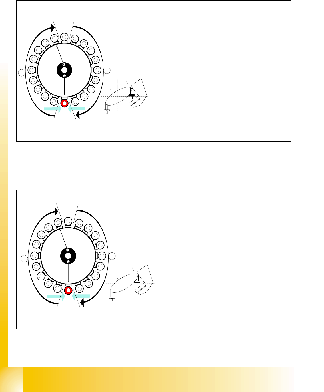
8.3.14 Placing the 1st Component
Fig. 8.3 - 14 Placing the 1st component
1
2
3
4
5
6
7
8
9
10
12
11
13
14
15
16
17
18
19
20
Segment 1
Segment 11
S
t
a
r
p
o
s
i
t
i
o
n
CO- Camera
CO- Sensor
CO - Sensor
A
B
Star turns to -> 360° (identical with 0° position)
When the star axis has turned to 360.000 digits, seg-
ment 1 is again in star-placement position.
– Vacuum check: holding force for component avai
lable?
– Z- axis starts to move downwards and then
– The component sensor checks the presence or
the height of the component at segment 1.
– The measured length before placement must be
larger than "nozzle length + comp.height - comp.
height tol."
– If errors occur, the Z-axis will be stopped and mo -
ved back.
1
2
3
4
5
6
7
8
9
10
12
11
13
14
15
16
17
18
19
20
Segment 1
Segment 11
S
t
a
r
p
o
s
i
t
i
o
n
CO- Camera
CO - Sensor
CO- Sensor
A
B
Star position 0°
– Vision system: optical centering of the 11th com-
ponent.
– Pickup / placement station: place 1st compo-
nent.
–
A, B (see previous chapter).
1 - 37
Student Guide SIPLACE X
Edition 09/2005 8 Collect&Place-Head 20
37
8.3.15 Component Sensor Checks Segment 1
Fig. 8.3 - 15 Component sensor checks after placement
The sequence described in Ch.8.2.13 to 8.2.15 is repeated for the remaining nozzles.
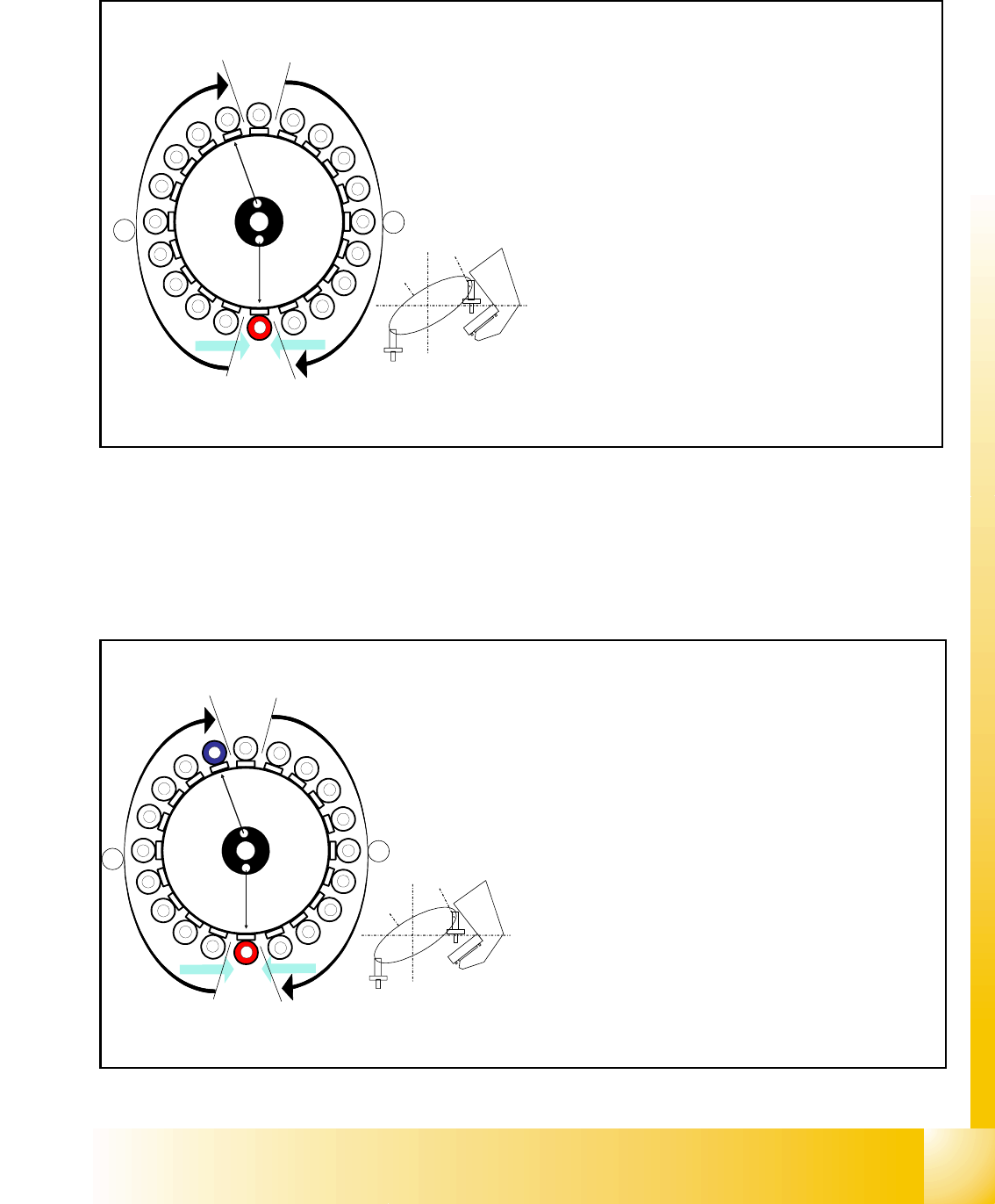
8.3.16 Placing the 10th Component
Fig. 8.3 - 16 Placing the 10th component
1
2
3
4
5
6
7
8
9
10
12
11
13
14
15
16
17
18
19
20
Segment 1
Segment 11
S
t
a
r
p
o
s
i
t
i
o
n
CO- Camera
CO - Sensor
CO- Sensor
A
B
Sternposition 0°
– Vision system: optical centering of the 11th com-
ponent.
– Pickup/placement station:
Z-axis moves upwards and sensor checks
whether component has been placed at seg-
ment 1.
–
A, B (see previous chapter).
– Vacuum check: whether vacuum has been
switched back on.
10
CO - Sensor
CO - Sensor
Segment 10
Segment 20
S
t
a
r
p
o
s
i
t
i
o
n
CO- Camera
1
2
3
4
5
6
7
8
9
11
12
13
14
15
16
17
18
19
20
A
B
Star position 162°
– Vision system: optical centering of the 20th compo-
nent
– Pickup / placement station: place 10th component.
(marked red (light grey) here)
– At the next step Visionsystem have to center opti-
cally the component at segment 1 on the other gan-
try. (marked blue here)
– Component sensor:
Checks before placement; if component is present
on nozzle / after placement; if the component has
been placed.
(see Ch. 8.2.13 to 8.2.15)
– A, B (see previous chapter)