SiplaceX4_en.pdf - 第403页
1 - 37 S tudent Guide SIPLACE X Edition 09/2005 8 Collect&Place-Head 20 37 8.3.15 Component Sensor Checks Segment 1 Fig. 8.3 - 15 Component sensor checks after placement The sequence describe d in Ch.8.2.13 to 8.2.15…
1 - 36
Student Guide SIPLACE X
8 Collect&Place-Head 20 Edition 09/2005
36
8.3.13 Component recognition at the 1
st
Segment by Component Sensor
Fig. 8.3 - 13 Checking the component before placement
8.3.14 Placing the 1st Component
Fig. 8.3 - 14 Placing the 1st component
1
2
3
4
5
6
7
8
9
10
12
11
13
14
15
16
17
18
19
20
Segment 1
Segment 11
S
t
a
r
p
o
s
i
t
i
o
n
CO- Camera
CO- Sensor
CO - Sensor
A
B
Star turns to -> 360° (identical with 0° position)
When the star axis has turned to 360.000 digits, seg-
ment 1 is again in star-placement position.
– Vacuum check: holding force for component avai
lable?
– Z- axis starts to move downwards and then
– The component sensor checks the presence or
the height of the component at segment 1.
– The measured length before placement must be
larger than "nozzle length + comp.height - comp.
height tol."
– If errors occur, the Z-axis will be stopped and mo -
ved back.
1
2
3
4
5
6
7
8
9
10
12
11
13
14
15
16
17
18
19
20
Segment 1
Segment 11
S
t
a
r
p
o
s
i
t
i
o
n
CO- Camera
CO - Sensor
CO- Sensor
A
B
Star position 0°
– Vision system: optical centering of the 11th com-
ponent.
– Pickup / placement station: place 1st compo-
nent.
–
A, B (see previous chapter).
1 - 37
Student Guide SIPLACE X
Edition 09/2005 8 Collect&Place-Head 20
37
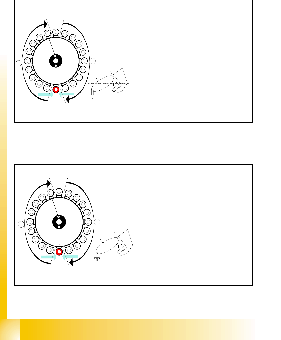
8.3.15 Component Sensor Checks Segment 1
Fig. 8.3 - 15 Component sensor checks after placement
The sequence described in Ch.8.2.13 to 8.2.15 is repeated for the remaining nozzles.
8.3.16 Placing the 10th Component
Fig. 8.3 - 16 Placing the 10th component
1
2
3
4
5
6
7
8
9
10
12
11
13
14
15
16
17
18
19
20
Segment 1
Segment 11
S
t
a
r
p
o
s
i
t
i
o
n
CO- Camera
CO - Sensor
CO- Sensor
A
B
Sternposition 0°
– Vision system: optical centering of the 11th com-
ponent.
– Pickup/placement station:
Z-axis moves upwards and sensor checks
whether component has been placed at seg-
ment 1.
–
A, B (see previous chapter).
– Vacuum check: whether vacuum has been
switched back on.
10
CO - Sensor
CO - Sensor
Segment 10
Segment 20
S
t
a
r
p
o
s
i
t
i
o
n
CO- Camera
1
2
3
4
5
6
7
8
9
11
12
13
14
15
16
17
18
19
20
A
B
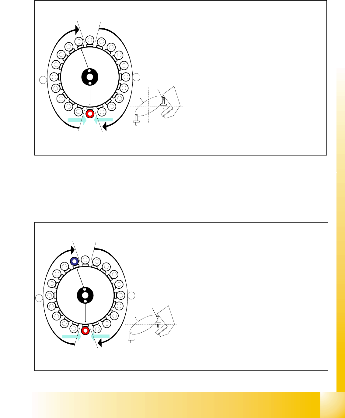
Star position 162°
– Vision system: optical centering of the 20th compo-
nent
– Pickup / placement station: place 10th component.
(marked red (light grey) here)
– At the next step Visionsystem have to center opti-
cally the component at segment 1 on the other gan-
try. (marked blue here)
– Component sensor:
Checks before placement; if component is present
on nozzle / after placement; if the component has
been placed.
(see Ch. 8.2.13 to 8.2.15)
– A, B (see previous chapter)
1 - 38
Student Guide SIPLACE X
8 Collect&Place-Head 20 Edition 09/2005
38
8.3.17 Placing the 11th Component
Fig. 8.3 - 17 Placing the 11th component
8.3.18 Placing the 20th Component
Fig. 8.3 - 18 Placing the 20th component
CO- Sensor
CO - Sensor
Segment 11
Segment 1
S
t
a
r
p
o
s
i
t
i
o
n
CO-Camera
11
12
13
14
15
16
17
18
19
1
2
3
5
6
7
8
9
10
4
20
A
B
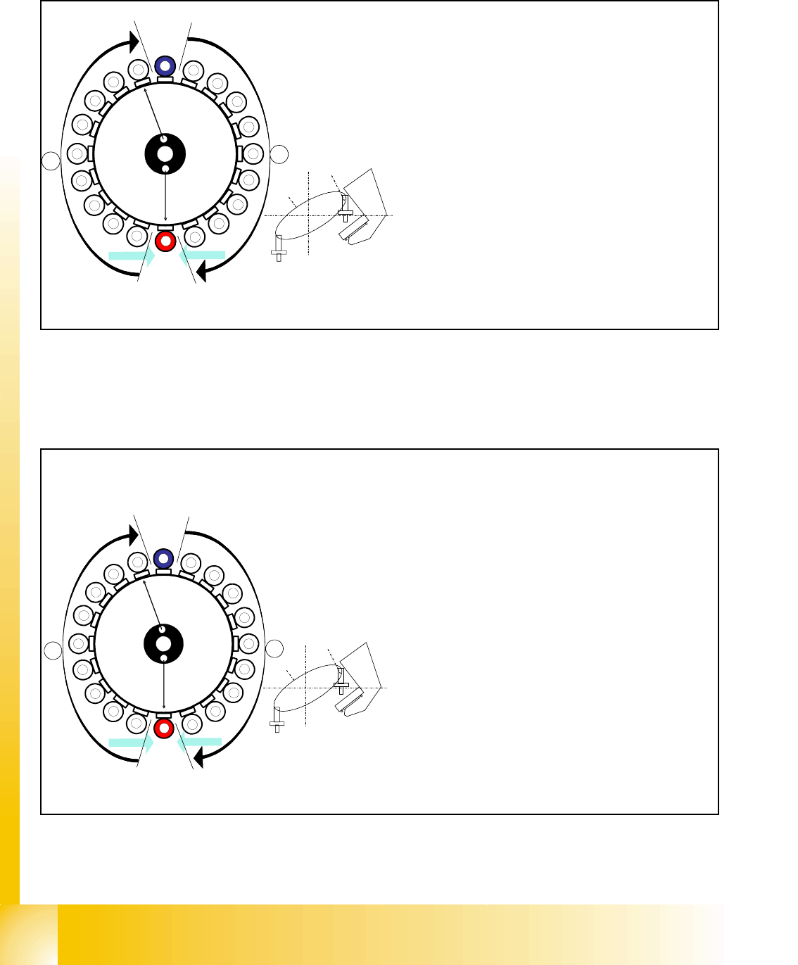
Star position 180°
– Vision system: optical centering of the 1st comp
o
on the other gantry (marked blue here)
– Pickup / placement station: place 11th compon
e
(marked red (light grey) here)
– Component sensor:
Checks before and after placement, whether
component is present on nozzle / has been placed
.
(see Ch. 8.2.13 to 8.2.15)
– A, B (see previous chapter)
CO - Sensor
CO - Sensor
Segment 20
Segment 10
S
t
a
r
p
o
s
i
t
i
o
n
CO-Camera
9
8
7
6
5
4
3
2
1
19
18
17
15
14
13
12
11
10
16
20
A
B
Star position 342°
– Vision system: optical centering of the 10th com-
ponent on the other gantry (marked blue here)
– Pickup / placement station: place 20th compo-
nent. (marked red here)
– Component sensor:
Checks before and after placement, whether
component is present on nozzle/has been
placed.
(see Ch. 8.2.13 to 8.2.15)
– A, B (see previous chapter)
– Synchronization:
After the 20th component this gantry Y-Axis con-
troller will enable the other gantry Y-Axis to move
to 1st placement position.