SiplaceX4_en.pdf - 第407页
1 - 41 S tudent Guide SIPLACE X Edition 09/2005 8 Collect&Place-Head 20 41 St art gantry axes to the pick up position of next feeder . Note: The V acuum is by default always on. – S tart signal for X/Y axes to move t…
1 - 40
Student Guide SIPLACE X
8 Collect&Place-Head 20 Edition 09/2005
40
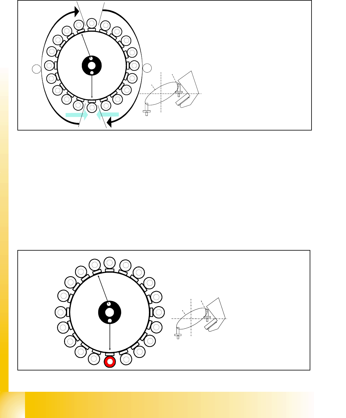
8.3.22 Positioning to Pickup/Placement Angle
Fig. 8.3 - 19 Positioning to pickup/placement angle
Positioning to the pickup/placement angle is performed individually by the DP master for each
segment of the C&P20 head, since each segment is equipped with its own DP station.
Each DP drive has its own measurement system for positioning.
Each DP stations have found their 0° position during the reference run, turns the segments in the
pickup/placement cycle in area
A, and after the vision system in area B, in their corrects place-
ment angle.
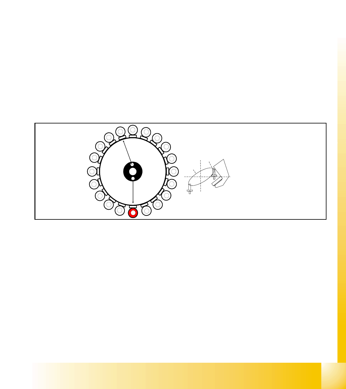
8.3.23 Detailed Standard Pickup Sequence: Z-axis Downwards
Fig. 8.3 - 20 Star position 0°: detailed pickup sequence: Z-axis downwards
1
2
3
4
5
6
7
8
9
10
12
11
13
14
15
16
17
18
19
20
Segment 1
Segment 11
S
t
a
r
p
o
s
i
t
i
o
n
CO-Camera
CO - Sensor
CO- Sensor
A
B
The 20 DP axes are controlled via the
„DP Master". The machine control
system can therefore effectively per-
form 4 actions simultaneously:
(1) Starts a certain rotary axis after
pickup/placement
(2) Starts a certain rotary axis after Vi-
sion
(3) Waits for a certain rotary axis be-
fore Vision
(4) Waits for a certain rotary axis be-
fore pickup/placement
1
2
3
4
5
6
7
8
9
10
12
11
13
14
15
16
17
18
19
20
C
O
-
C
a
m
e
r
a
Segment 1
S
e
g
m
e
n
t
1
1
S
t
a
r
p
o
s
i
t
i
o
n
1 - 41
Student Guide SIPLACE X
Edition 09/2005 8 Collect&Place-Head 20
41
Start gantry axes to the pick up position of next feeder.
Note:
The Vacuum is by default always on.
– Start signal for X/Y axes to move to next feeder.
End signal X, Y axes:
– If X, Y end signals exist
Z-axis starts:
– Z-axis starts positioning downwards
End signal star axes:
– Activate vacuum check: segment open threshold ? YES
because of Z-axis movement:
– Measurement value for nozzle length "empty"
Axis controller:
– Enable "light barrier down"
Light barrier down switches:
– End signal Z-axis positioning downwards
– Height value for pickup height optimization
8.3.24 Detailed Standard Pickup Sequence: Z-axis Upwards
Fig. 8.3 - 21 Detailed pickup sequence: Z-axis upwards
LB down switches:
– Vacuum Threshold comp. picked reached? YES
Z-axis starts:
– Z-axis starts positioning upwards
because of Z-axis movement:
– Z-axis position value; nozzle length + comp.height measurement
threshold reached?
YES
Z-Axis position in safety area:
– reset lightbarrier state, start X-, Y-Gantry axes, start component feeder (communication to
feeder table)
Vacuum check:
– vacuum threshold for holding circuit reached? YES
– this start Star axis
1
2
3
4
5
6
7
8
9
10
12
11
13
14
15
16
17
18
19
20
C
O
-
C
a
m
e
r
a
Segment 1
S
eg
m
ent
1
1
S
t
a
r
p
o
s
i
t
i
o
n
1 - 42
Student Guide SIPLACE X
8 Collect&Place-Head 20 Edition 09/2005
42
8.3.25 Standard Placement Mode: Z-Axis Downwards
Fig. 8.3 - 22 Detailed component placement sequence: Z-axis downwards
In this mode (light barrier down) the placement force at the C&P 20 head is around 2N.
End signal for X and Y axes:
Z-axis starts:
– Z-axis positioning downwards
– Component sensor checks nozzle length with component. Threshold reached?
YES
End signal for star axis:
– Performs vacuum test "before placement" Vacuum closed threshold reached? YES
to determine whether the component is held by holding force on the nozzle.
Axis controller:
– Enable signal for "light barrier down" function
LB down switches:
– End signal Z-axis positioning downwards;
– Digital pressure control valve: switches air kiss ON
– Pickup/placement position; air kiss threshold ’place component’ reached?
– ...
1
2
3
4
5
6
7
8
9
10
12
11
13
14
15
16
17
18
19
20
C
O
-
C
am
e
r
a
Segment 1
S
e
g
m
e
n
t
1
1
S
t
a
r
p
o
s
i
t
i
o
n