SiplaceX4_en.pdf - 第412页
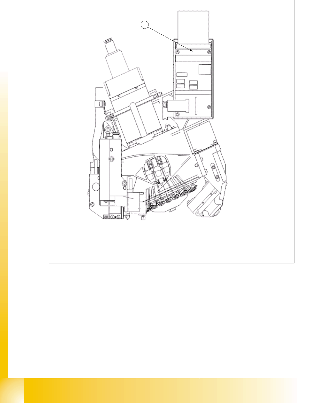
1 - 46 S tudent Guide SIPLACE X 8 Collect&Place-Head 20 Edition 09/2005 46 8.4.1.2 Arrangement of Intermediate distributor 20 C&P head (003 005158-0X) Abb. 8.4 - 2 Intermediate distributor board C&P 20 head L…
1 - 45
Student Guide SIPLACE X
Edition 09/2005 8 Collect&Place-Head 20
45
8.4 Adjustments
8.4.1 Description of the PCB boards on the C&P head
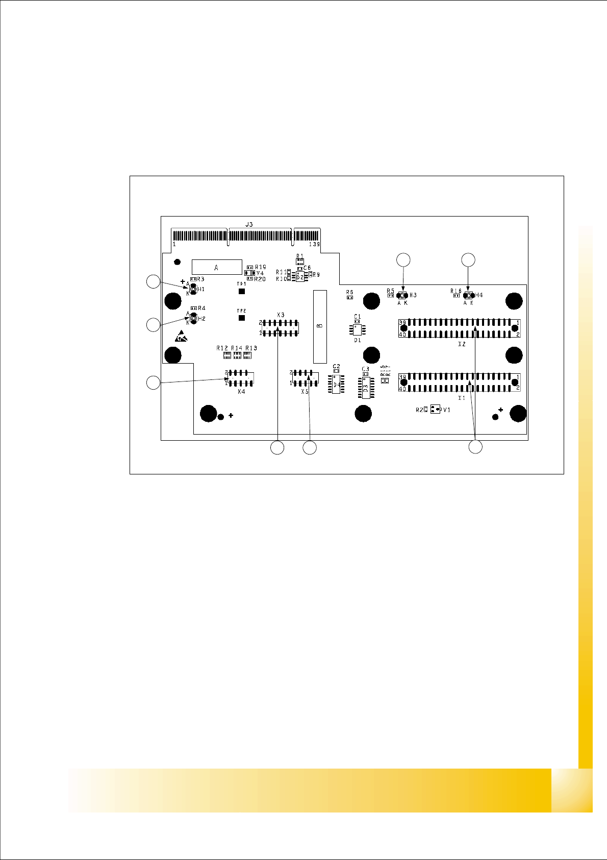
8.4.1.1 Head adapter 20 C&P head
Abb. 8.4 - 1 Head adapter for 20 C&P placement head
Legend:
(1) X1, X2 connection to intermediate distributor board
(2) X5 Track signals of the Z-axis
(3) X3 Test connector : Seriell Parallel Interface (SPI)- Bus
(4) X4 Track signals of the Star axis
(5) H2 LED (green) to indicate 24V of DP- drives
(6) H1 LED (red) to indicate 24V at C&P20 head
(7) H3 LED (green) to indicate component Sensor
(8) H4 LED (red) to indicate Hardware- error C&P20 head
1
23
4
5
6
7 8
1 - 47
Student Guide SIPLACE X
Edition 09/2005 8 Collect&Place-Head 20
47
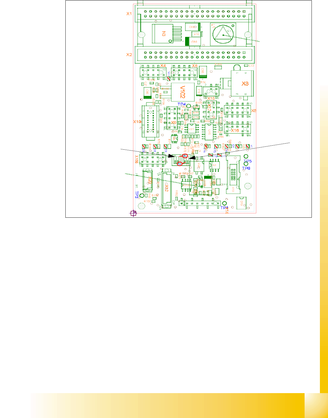
Abb. 8.4 - 3 Intermediate distributor - connector description
Following voltages and signals are distributed from intermediate distributor to the single subunits
of the head respective to the headboard :
Connector X1, 40-polig : Connector X1 from the head adapter board
Connector X2, 40-polig : Connector X2 from the head adapter board
Connector X3 : Supply for the Star drive
Connector X4 : Incremental encoder Star axis
Connector X6 : Incremental encoder Z-axis
Connector X8 : Supply for the Z drive
Connector X9 : Connector for the component sensor
Connector X12 : Connector for pressure regulator valve
Connector X14 : Test Connector X14_3 :+5V/X14_4 :+15V/X14_5:-15V/X14_7:24V for DP drives
Connector X15 : Connector for the retract unit
Connector X16 : Internal CAN BUS C&P20
S1
S2