SiplaceX4_en.pdf - 第414页
1 - 48 S tudent Guide SIPLACE X 8 Collect&Place-Head 20 Edition 09/2005 48 S1 (left switch) S2 (right switch): T ab. 8.4 - 2 S2 (right switch) Please Note: The bold ex pressions are the standard adjustments of the sw…
1 - 47
Student Guide SIPLACE X
Edition 09/2005 8 Collect&Place-Head 20
47
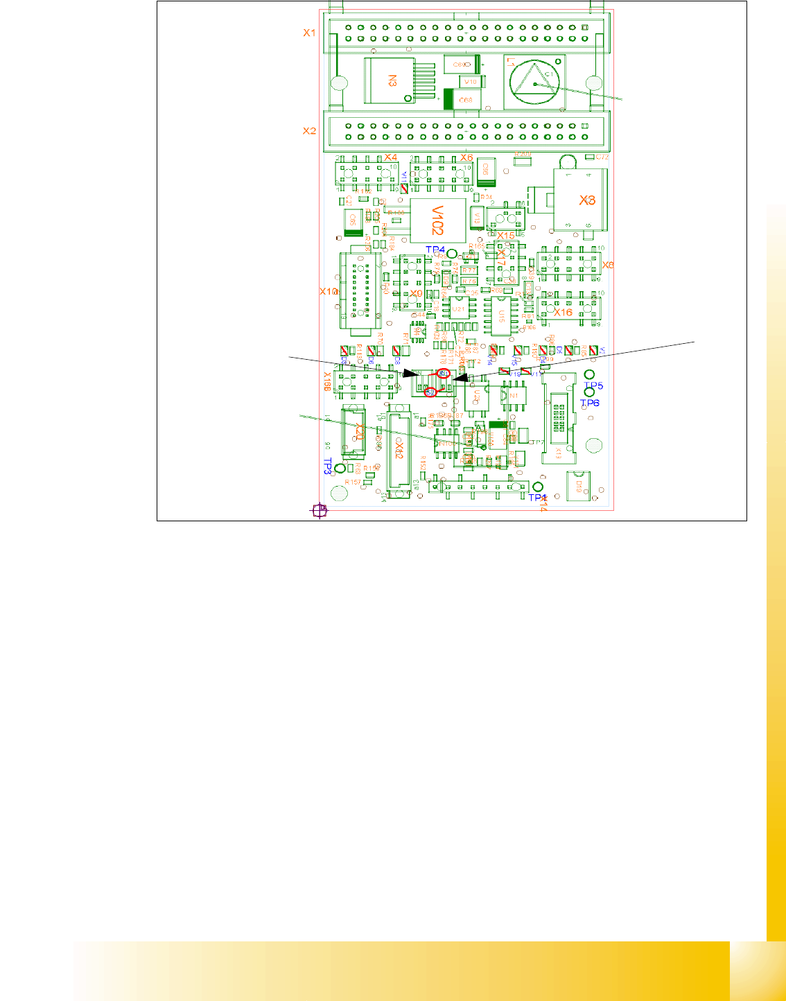
Abb. 8.4 - 3 Intermediate distributor - connector description
Following voltages and signals are distributed from intermediate distributor to the single subunits
of the head respective to the headboard :
Connector X1, 40-polig : Connector X1 from the head adapter board
Connector X2, 40-polig : Connector X2 from the head adapter board
Connector X3 : Supply for the Star drive
Connector X4 : Incremental encoder Star axis
Connector X6 : Incremental encoder Z-axis
Connector X8 : Supply for the Z drive
Connector X9 : Connector for the component sensor
Connector X12 : Connector for pressure regulator valve
Connector X14 : Test Connector X14_3 :+5V/X14_4 :+15V/X14_5:-15V/X14_7:24V for DP drives
Connector X15 : Connector for the retract unit
Connector X16 : Internal CAN BUS C&P20
S1
S2
1 - 48
Student Guide SIPLACE X
8 Collect&Place-Head 20 Edition 09/2005
48
S1 (left switch)
S2 (right switch):
Tab. 8.4 - 2 S2 (right switch)
Please Note:
The bold expressions are the standard adjustments of the switchs.
Meaning of LED´s : 8
Nr. Function Switch position =0 (open) Switch position =1 (clossed)
S1.1 CAN-Test
Normal mode: 1-wire-head
CAN-Bus only for Motherboard
ready
Test mode: without Motherboard pos-
sible
S1.2
CAN-ID- change
over switch press.
control valve
Pressure regualtor valve con-
nected to CAN-ID 0x6B0
pressure regualtor valve connected to
CAN-ID 0x6B0 (Test mode)
Tab. 8.4 - 1 S1 (left switch)
Nr. Function Switch position =0 (open) Switch position =1 (clossed)
S2.1
Z-bottom-Sensor :
LED in ON- OFF
mode
LED mode in ON or OFF mode
to activate
LED always ON (Test mode, e.g. to
measure activated sleeve spring))
S2.2
Z-bottom-Sensor :
LED in blinking
mode LED mode blinking when active
LED is with light barrier bottom ON
Nr. Function ON OFF
D3 +5V present missing
D4 Z-bottom trriggered Not triggered
D5 Z-bottom-Reset Reset Not Reset
D6 +15V present missing
D7 +24V_IN
D8 -15V present missing
V2 Z-retract valve triggered (down) not triggered (up)
V11
Enable pressure regu-
lator valve
error at pressure regula-
tor valve pressure regulator valve OK
V14 +24V present missing
V15 +24V_DP 24 V supply ON 24 V supply OFF
V16/17 GND
Tab. 8.4 - 3 Description LED´s
1 - 49
Student Guide SIPLACE X
Edition 09/2005 8 Collect&Place-Head 20
49
Test pin : 8
Test Connector X14 : 8
Nr. Function
TP1 GND
TP3 Voltage pressure signal pressure regulator valve internal
TP4 output voltage I/U- converter Z-bottom
TP5 Z-bottom
TP6 Z-at top / Z-at bottom-Reset
Tab. 8.4 - 4 Test pin
Pin Signal
1CAN_RX
2GND
3+5V
4+15V
5 -15V
6 X2_11
7 24V_DP
8 Z-at top / Z-at bottom-Reset
Tab. 8.4 - 5 Test Connector X14