SiplaceX4_en.pdf - 第415页
1 - 49 S tudent Guide SIPLACE X Edition 09/2005 8 Collect&Place-Head 20 49 T est pin : 8 T est Connector X14 : 8 Nr . Function TP1 GND TP3 V oltage pressure signal pressure regulator valve internal TP4 output voltage…
1 - 48
Student Guide SIPLACE X
8 Collect&Place-Head 20 Edition 09/2005
48
S1 (left switch)
S2 (right switch):
Tab. 8.4 - 2 S2 (right switch)
Please Note:
The bold expressions are the standard adjustments of the switchs.
Meaning of LED´s : 8
Nr. Function Switch position =0 (open) Switch position =1 (clossed)
S1.1 CAN-Test
Normal mode: 1-wire-head
CAN-Bus only for Motherboard
ready
Test mode: without Motherboard pos-
sible
S1.2
CAN-ID- change
over switch press.
control valve
Pressure regualtor valve con-
nected to CAN-ID 0x6B0
pressure regualtor valve connected to
CAN-ID 0x6B0 (Test mode)
Tab. 8.4 - 1 S1 (left switch)
Nr. Function Switch position =0 (open) Switch position =1 (clossed)
S2.1
Z-bottom-Sensor :
LED in ON- OFF
mode
LED mode in ON or OFF mode
to activate
LED always ON (Test mode, e.g. to
measure activated sleeve spring))
S2.2
Z-bottom-Sensor :
LED in blinking
mode LED mode blinking when active
LED is with light barrier bottom ON
Nr. Function ON OFF
D3 +5V present missing
D4 Z-bottom trriggered Not triggered
D5 Z-bottom-Reset Reset Not Reset
D6 +15V present missing
D7 +24V_IN
D8 -15V present missing
V2 Z-retract valve triggered (down) not triggered (up)
V11
Enable pressure regu-
lator valve
error at pressure regula-
tor valve pressure regulator valve OK
V14 +24V present missing
V15 +24V_DP 24 V supply ON 24 V supply OFF
V16/17 GND
Tab. 8.4 - 3 Description LED´s

1 - 49
Student Guide SIPLACE X
Edition 09/2005 8 Collect&Place-Head 20
49
Test pin : 8
Test Connector X14 : 8
Nr. Function
TP1 GND
TP3 Voltage pressure signal pressure regulator valve internal
TP4 output voltage I/U- converter Z-bottom
TP5 Z-bottom
TP6 Z-at top / Z-at bottom-Reset
Tab. 8.4 - 4 Test pin
Pin Signal
1CAN_RX
2GND
3+5V
4+15V
5 -15V
6 X2_11
7 24V_DP
8 Z-at top / Z-at bottom-Reset
Tab. 8.4 - 5 Test Connector X14

1 - 50
Student Guide SIPLACE X
8 Collect&Place-Head 20 Edition 09/2005
50
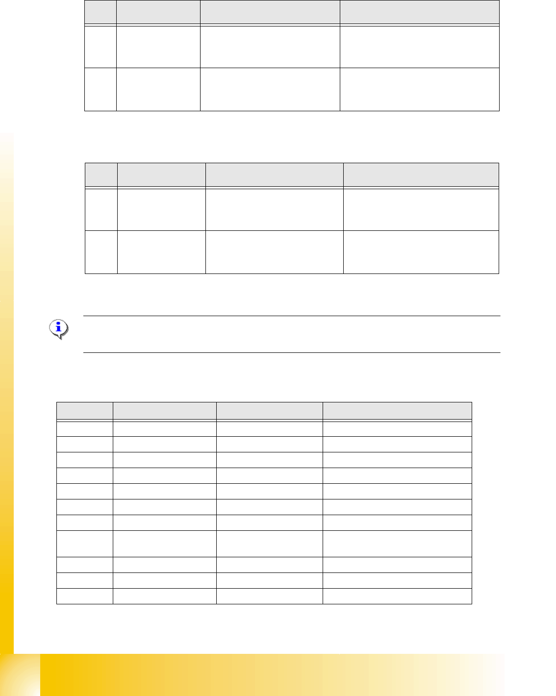
8.4.2 Spare part overview and settings at 20 C&P head
Spare part name Tools Setting valve
Component camera
calibration tool and Sitest
Allen key
calibrate the digital compo-
nent camera
Digital Vacuumgenerator
(pressure regulator valve)
Caccia
Allen key Firmware download in Sitest
Incremental encoder Z-Axis feeler gauge 0,4mm
- 0,4mm distance between In-
cemental encoder and scale
Z-drive complete
-Incremental encodert
-Linear drive Allen key
Press Z-drive against the limit
and fix.
- determine Z-zero point cor-
rection autom. at reference
run
Retract unit Z-Axis Allen key
The holder on the retract unit
adjust to the top position of
the frame from the retract
unit, so that the Z-axis is in the
top position and the star can
move.
Light barrier Z-Axis bottom parallel pin 1,0mm distance 1,0mm
Component sensor
Sitest
Allen key
Check function
Firmware download possible
Silencer 10 mm wrench ---
Vacuum holding circuit complete
-Vacuum generator
- Silencer
- Special screw
10 mm wrench
Allen key ---
Segment with DP drive
A pair of tweezers with plastic
points
Allen key
No settings.
Firmware download possible
Calibrate the segment offset
(above, below)
Star complete Allen key
Determine the Z- and Star
zero point correction
Tab. 8.4 - 6 Overview Adjustments and settings