SiplaceX4_en.pdf - 第417页
1 - 51 S tudent Guide SIPLACE X Edition 09/2005 8 Collect&Place-Head 20 51 8.5 Nozzle changer The Siplace X is sup plied with 6 segment -, 12 segment- or 20 segment Collect&Place heads. As an option, nozzle chang…
1 - 50
Student Guide SIPLACE X
8 Collect&Place-Head 20 Edition 09/2005
50
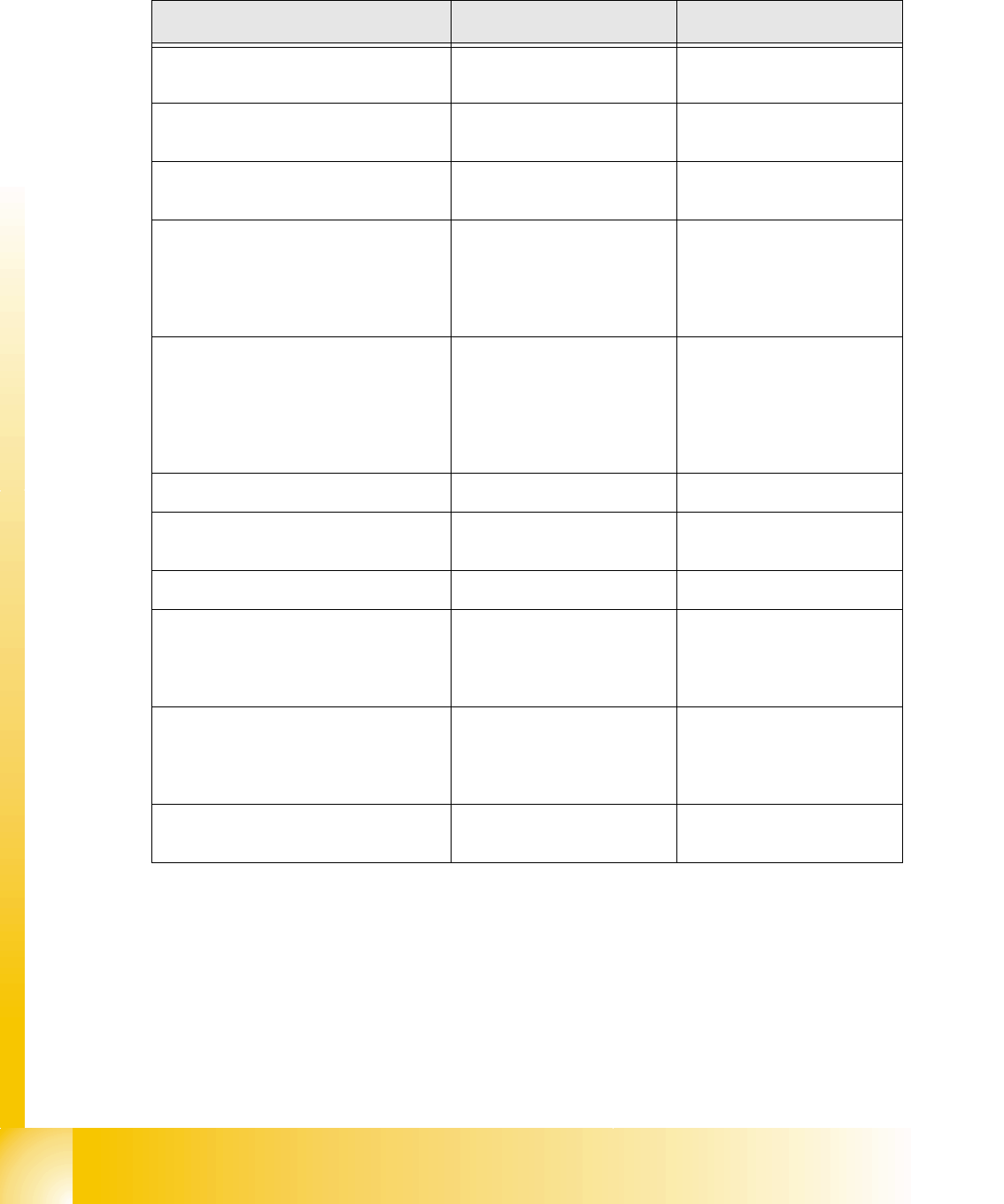
8.4.2 Spare part overview and settings at 20 C&P head
Spare part name Tools Setting valve
Component camera
calibration tool and Sitest
Allen key
calibrate the digital compo-
nent camera
Digital Vacuumgenerator
(pressure regulator valve)
Caccia
Allen key Firmware download in Sitest
Incremental encoder Z-Axis feeler gauge 0,4mm
- 0,4mm distance between In-
cemental encoder and scale
Z-drive complete
-Incremental encodert
-Linear drive Allen key
Press Z-drive against the limit
and fix.
- determine Z-zero point cor-
rection autom. at reference
run
Retract unit Z-Axis Allen key
The holder on the retract unit
adjust to the top position of
the frame from the retract
unit, so that the Z-axis is in the
top position and the star can
move.
Light barrier Z-Axis bottom parallel pin 1,0mm distance 1,0mm
Component sensor
Sitest
Allen key
Check function
Firmware download possible
Silencer 10 mm wrench ---
Vacuum holding circuit complete
-Vacuum generator
- Silencer
- Special screw
10 mm wrench
Allen key ---
Segment with DP drive
A pair of tweezers with plastic
points
Allen key
No settings.
Firmware download possible
Calibrate the segment offset
(above, below)
Star complete Allen key
Determine the Z- and Star
zero point correction
Tab. 8.4 - 6 Overview Adjustments and settings
1 - 51
Student Guide SIPLACE X
Edition 09/2005 8 Collect&Place-Head 20
51
8.5 Nozzle changer
The Siplace X is supplied with 6 segment -, 12 segment- or 20 segment Collect&Place heads. As
an option, nozzle changer can be installed for each collect&place head type. This enables the noz-
zle configuration to be changed quickly, thus allowing the collect&place head to be quickly
adapted to the needs of the placement process. The nozzle changer configuration for C&P20
looks as follows.
8.5.1 Nozzle changer for C&P 20 head
The nozzle changer consists of six magazines, each with twelve nozzle garages (see Fig. 8.5 -
2),how the individual garages freely are configurable. Every magazine is clampt on the basic body
with 4 push buttons. The magazine can be removed by the activity one for tipping over lever (per
magazine of one).The magazines are seated on a common support and each magazine is cen-
tered using two parallel pins and another pin is used to move the magazine shutter. A visual report
(green LED) shows, with the help of the built-in microswitches, whether all magazines are locked
correctly at the nozzle changer carrier.
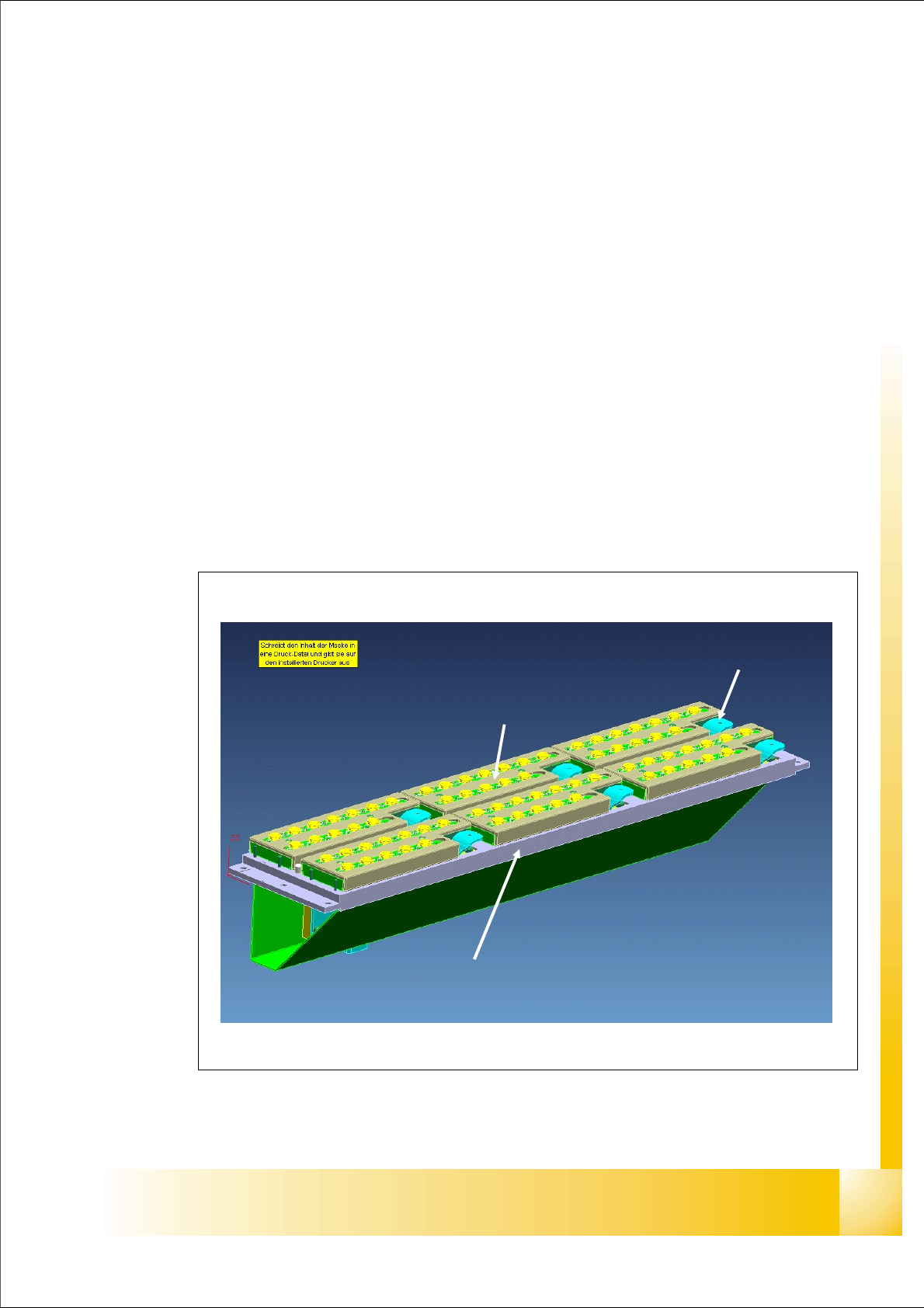
Fig. 8.5 - 1 main view - nozzle changer and nozzle magazin 20 segment C&P head
tipping over lever to remove the
magazine
nozzle changer basic body
magazine
1 - 52
Student Guide SIPLACE X
8 Collect&Place-Head 20 Edition 09/2005
52
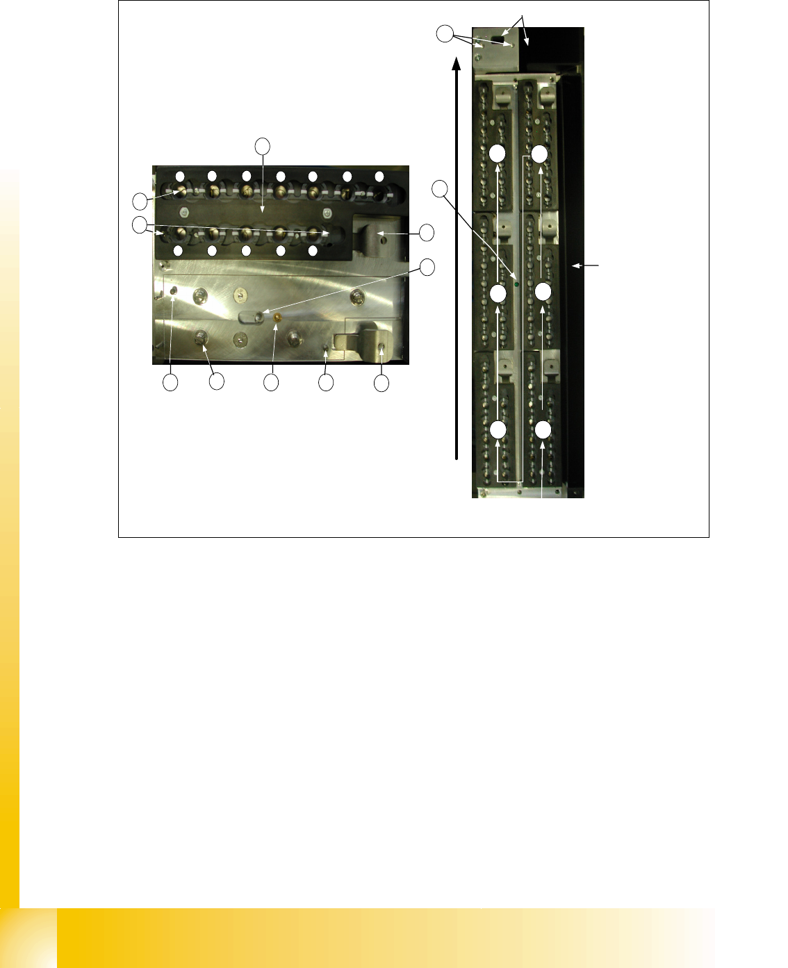
8.5.2 Detail view of nozzle changer C&P 20 head
Fig. 8.5 - 2 Detail view of nozzle changer 20 segment C&P head
Legend left picture in Fig.8.5-2
(1) X/Y position of calibration fiducial (2) Locking plate
(3) Nozzle garage (4) The parallel pins to the centering maga-
zine
(5) Microswitch for magazine recognition (6) Tipping over lever to remove the magazine
(7) Locking Pin of magazine (8) 4 push button to the mount on the nozzle
changer carrier
(9) green LED check for a right mount of all
magazines on the nozzle changer carrier
(10) X/Y position of calibration fiducial of
nozzle reject box
conveyor direction
1
2
3
4
5
6
way of counting of the
magazines
nozzle reject box
component reject box
1
2 3
4 5 6 7
8 9 10 11 12
4
8
5 4
6
7
6
2
3
1
9
10