SiplaceX4_en.pdf - 第419页
1 - 53 S tudent Guide SIPLACE X Edition 09/2005 8 Collect&Place-Head 20 53 8.5.2.1 Nozzle reject unit For the C&P 20 head reject un it we integreted a p art to check and fixed the correct position of the nozzle t…
1 - 52
Student Guide SIPLACE X
8 Collect&Place-Head 20 Edition 09/2005
52
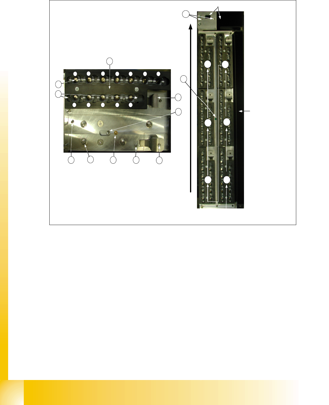
8.5.2 Detail view of nozzle changer C&P 20 head
Fig. 8.5 - 2 Detail view of nozzle changer 20 segment C&P head
Legend left picture in Fig.8.5-2
(1) X/Y position of calibration fiducial (2) Locking plate
(3) Nozzle garage (4) The parallel pins to the centering maga-
zine
(5) Microswitch for magazine recognition (6) Tipping over lever to remove the magazine
(7) Locking Pin of magazine (8) 4 push button to the mount on the nozzle
changer carrier
(9) green LED check for a right mount of all
magazines on the nozzle changer carrier
(10) X/Y position of calibration fiducial of
nozzle reject box
conveyor direction
1
2
3
4
5
6
way of counting of the
magazines
nozzle reject box
component reject box
1
2 3
4 5 6 7
8 9 10 11 12
4
8
5 4
6
7
6
2
3
1
9
10
1 - 53
Student Guide SIPLACE X
Edition 09/2005 8 Collect&Place-Head 20
53
8.5.2.1 Nozzle reject unit
For the C&P 20 head reject unit we integreted a part to check and fixed the correct position of the
nozzle to the segment interface.
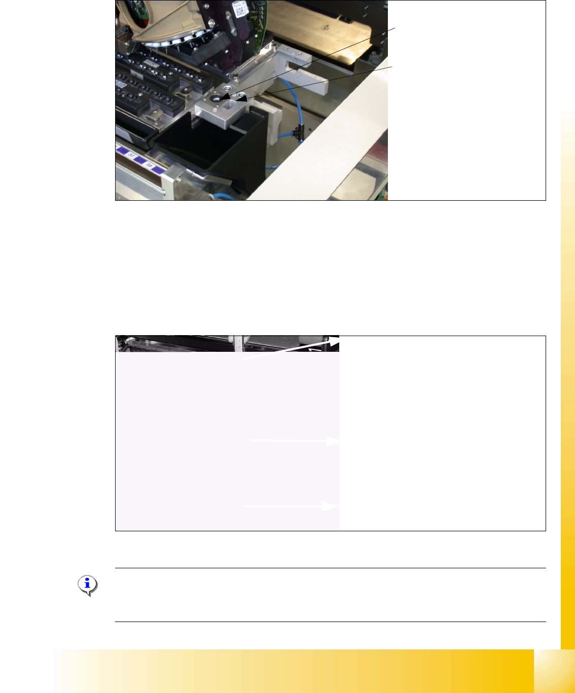
8.5.3 Adjustment of the height of the nozzle changer C&P 20 head
To get the correct safe distance between head (Component sensor) and nozzle changer is it nec-
essary to measure and adjust the height between mounting surface docking unit and the linear
guide of the X axis.
The distance have to
150,0mm +/-0,2mm. The support of the nozzle changer carrier has to be
adjusted with washers in its height until the the nominal distance is acchieved and then you can
mount the nozzelchangetr.
Fig. 8.5 - 3 Adjusting of nozzle changer at C&P20- head
Please Note for assembling the nozzle changer :
During assembling the nozzle changer keep attention that the component reject box can be easily
removed. Don´t use to long screws, otherwise the component reject box will be fixed.
Nozzle reject unit
Check the nozzle to the segment
interface
Reject nozzles
The height of the nozzle reject
unit have to adjust at
140,0 +\-
0,3 mm. The measurement pro-
cedure is the same like the
nozzle changer (see image be-
low).
Calliper
Top edge of the below linear guide
X-Axis
Mounting surface of the nozzle chan-
ger.
150,0mm +/-0,2
1 - 54
Student Guide SIPLACE X
8 Collect&Place-Head 20 Edition 09/2005
54
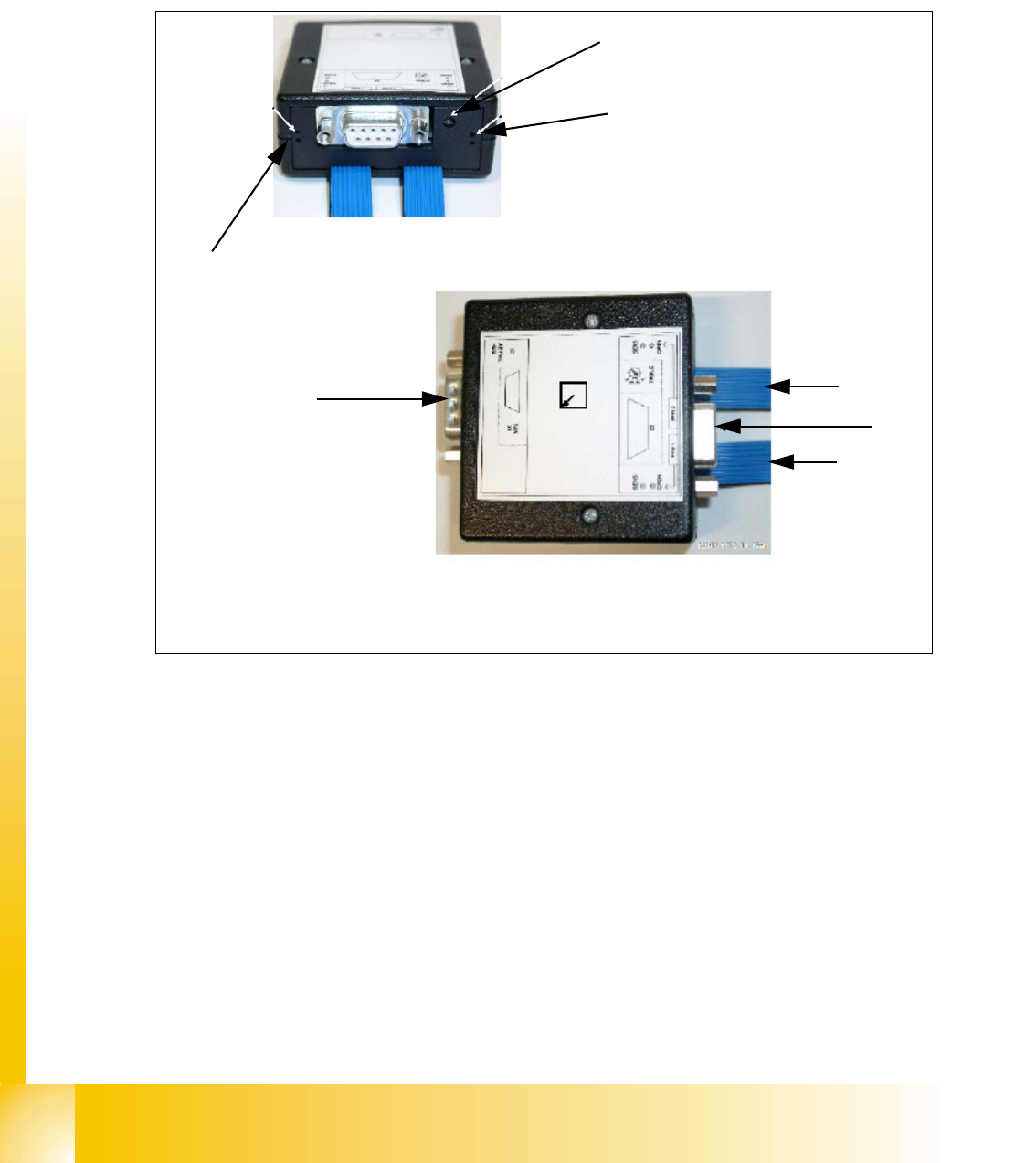
8.5.4 Control unit for nozzle changer of the C&P heads
The nozzle changer are controlled depend on the configuration of the location at the machine via
CAN Bus (SLIO Main- und Sub-Distributor). In future with the SW 505 the nozzle changer are con-
trolled via the "One Wire Bus". Soleniods control the pneumatic rotary drives and open or close
the nozzle changer.
Legende
(1) SUB-D connector machine CAN Bus (2) SUB-D connector Option ( reject boxes / 24 V)
(3) ribbon cable nozzle changer 1 (4) ribbon cable nozzle changer 2
Location
code
LED check DLM nozzle
changer 2
1
2
3
4
LED check DLM
nozzlechanger 1