SiplaceX4_en.pdf - 第42页
1 - 18 S tudent Guide SIPLACE X 2 Overview Edition 09/2005 18 2.2.5.3 Example of Axis Unit for X3/ X2 with T win Head in Placement Area 2 Fig. 2.2 - 7 Axis unit BB2 with twin head Key (1) DC/DC converter 5V/15A for axis …
1 - 17
Student Guide SIPLACE X
Edition 09/2005 2 Overview
17
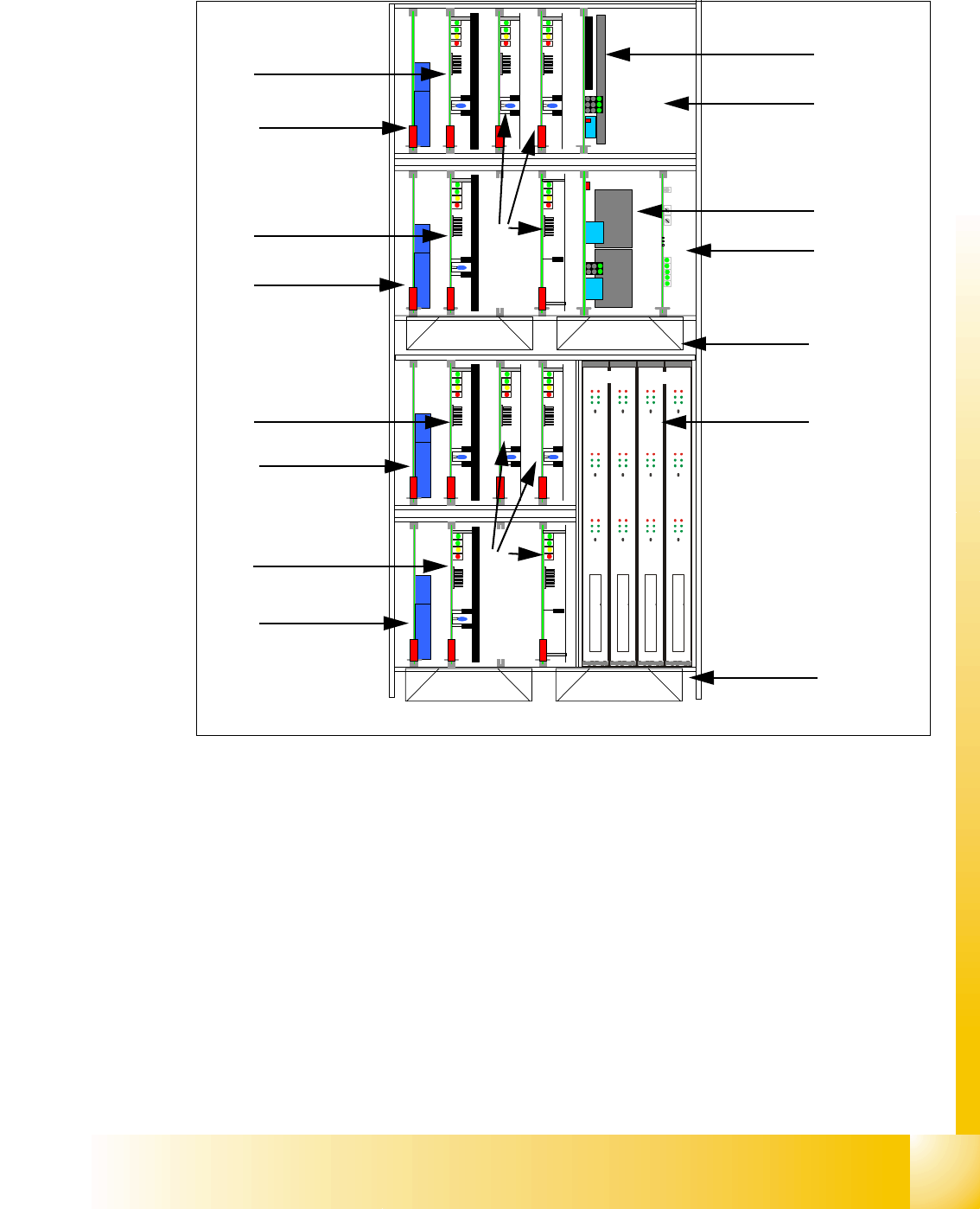
2.2.5.2 Example of Axis Unit for X4/ X3 with Two DLM Heads in Placement Area 1
Fig. 2.2 - 6 Axis unit PA1 with DLM Heads
Key
(1) DC/DC converter 5V/15A for axis unit (2)
Ballast circuit board, only in axis unit BB2
(3) DC/DC converter +/-15V for gantries and
head interface, 5V CAN BUS
(4) Anti crash board
(5) Fan unit (blow downwards) (6) Axis boards A363
(7) Servo boards X-axis, placement area 1 for gan-
tries 1/4
(8) Servo boards Y-axis, placement area 1 for gan-
tries 1/4
(9) Brake board for each X and Y axis
(10) Servo boards for star-/Z-/DP-axes
TBS 250/10X
TBS 250 /20Y
DBM/3P-06
SDS 120/2.5S1-03
5 V / 15A 15V/1,7A 15V/ 1,7A
SDS 60/1D1-02
DBM/3P-06
TBS 250/10X
TBS 250 /20Y
DBM/3P-06
SDS 120/2.5S1-03
SDS 60 3Z1-02
SDS 60/1D1-02
DBM/3P-06
SDS 60/3Z1-02
15 V / 5A 15 V / 5A
Anti crash board
Portal 1
Portal 4
X Z
X
Z
Y
dp
X
Stern Frei
dp
Stern Frei
1
2
3
4
5
6
7
9
8
9
7
9
8
9
Placement area 1
Gantry 1
Placement area 1
Gantry 4
5
10
10
1 - 18
Student Guide SIPLACE X
2 Overview Edition 09/2005
18
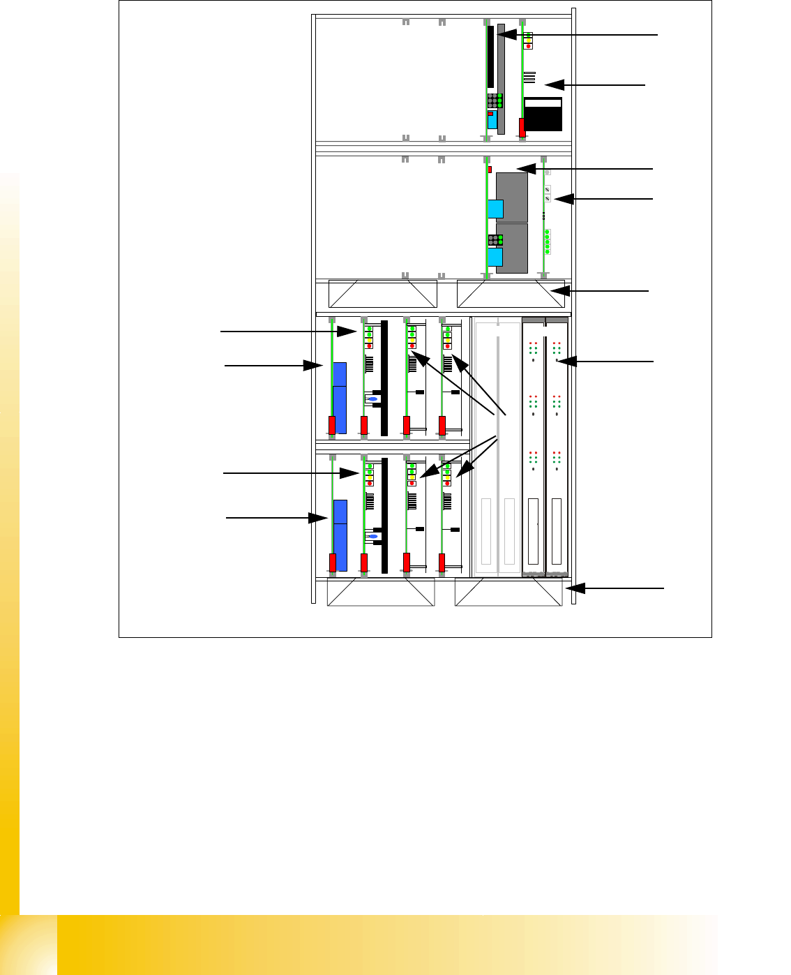
2.2.5.3 Example of Axis Unit for X3/ X2 with Twin Head in Placement Area 2
Fig. 2.2 - 7 Axis unit BB2 with twin head
Key
(1) DC/DC converter 5V/15A for axis unit
(2) Ballast circuit board
(3) DC/DC converter +/-15V for gantries and
head interface, 5V CAN BUS
(4) Anti crash board
(5) Fan unit (blow downwards) (6) Axis boards A363
(7) Servo boards X-axis, placement area 2 for
gantry 3
(8) Servo boards Y-axis, placement area 2 for
gantry 3
(9) Brake board for each X and Y axis (10) Servo boards Z/D-axis twin head
TBS 250/10X
DBM/3P-06
SDS 60/1Z1 (f. Segment 2)
DBM/3P-06
SDS 60/0,5D1 (f. Segment 2)
TBS 250/20Y
SDS 60/1Z1 (f. Segment 1)
SDS 60/0,5D1 (f. Segment 1)
5 V / 15A 15V/1,7A 15V/ 1,7A
15 V / 5A 15 V / 5A
Anti crash board
BS 250 / 1000 -03
X
Y
Z 2
dp 1
Z 1
dp 2
Portal 3
Portal 2
1
2
3
4
5
6
7
9
8
9
Placement area 2
Only for gantry 2 in
X4
Placement area 2
Gantry 3
5
10
1 - 19
Student Guide SIPLACE X
Edition 09/2005 2 Overview
19
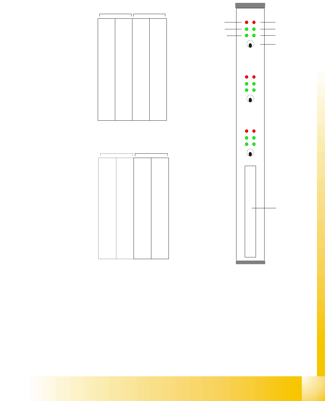
2.2.5.4 Axis Card A363
Abbreviation:
X = X-axis and gantry number
Z1= Z-axis for twin head module 1
Y= Y-axis and gantry number D
1= Rotary axis for twin head modules 1
S= Star axis and gantry number for C&P head Z
2= Z-axis for twin head module 2
Z= Z-axis and gantry number for C&P head D
2= Rotary axis for twin head module 2
DP= Swivel axis and gantry number for C&P
head
The DP/D-axis controller is not used in C&P20
heads.
Counter error
Zero puls
End signal
Common error,
Board error
Initialisation
Servo On
Axis switch off/on
Axis 0
Axis 1
Axis 2
Interface
Axis test box
X 1
Address
0
Y 1
Address
1
S 1
Address
2
Z 1
Address
3
DP 1
Address
5
free
Address
5
X 4
Address
6
Y 4
Address
7
S 4
Address
8
Z 4
Adress
9
DP 4
Address
10
free
Address
11
Gantry 1 Gantry 4
Placement area PA 1
Servos 'bottom'Servos 'top'
X 2
Address
16
Y 2
Address
17
S 2
Address
18
Z 2
Address
19
DP 2
Address
20
free
Address
21
X 3
Address
22
Y 3
Address
23
S3/Z
2
Address
24
Z/Z
1
Address
25
DP/D
1
Address
26
/D
2
Addres
27
Gantry 2 not used Gantry 3
Placement area PA 2
Servos 'bottom'Servos 'top'