SiplaceX4_en.pdf - 第421页
1 - 55 S tudent Guide SIPLACE X Edition 09/2005 8 Collect&Place-Head 20 55 8.5.5 Pneumatic plan for nozzle changer Fig. 8.5 - 4 Pressure air supply for the nozzle changer The air pressure supply of the nozzle changer…
1 - 54
Student Guide SIPLACE X
8 Collect&Place-Head 20 Edition 09/2005
54
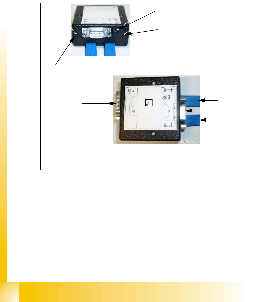
8.5.4 Control unit for nozzle changer of the C&P heads
The nozzle changer are controlled depend on the configuration of the location at the machine via
CAN Bus (SLIO Main- und Sub-Distributor). In future with the SW 505 the nozzle changer are con-
trolled via the "One Wire Bus". Soleniods control the pneumatic rotary drives and open or close
the nozzle changer.
Legende
(1) SUB-D connector machine CAN Bus (2) SUB-D connector Option ( reject boxes / 24 V)
(3) ribbon cable nozzle changer 1 (4) ribbon cable nozzle changer 2
Location
code
LED check DLM nozzle
changer 2
1
2
3
4
LED check DLM
nozzlechanger 1
1 - 55
Student Guide SIPLACE X
Edition 09/2005 8 Collect&Place-Head 20
55
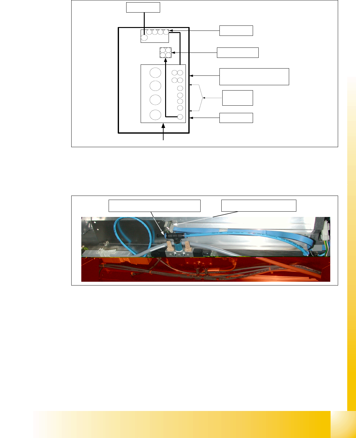
8.5.5 Pneumatic plan for nozzle changer
Fig. 8.5 - 4 Pressure air supply for the nozzle changer
The air pressure supply of the nozzle changer will be assembled by the T-piece as shown in the
picture below. A additional Y- piece is necessary for the optional 2
nd
Nozzle changer carrier.
Fig. 8.5 - 5 Air pressure connection of the nozzle changer
The DLM nozzle changers are connected to 2.5 bar (loopedhose in the picture). The C&P20 noz-
zelchanger is connected to 4.5 bar.
3
4
2
1
Gantry 1 - 4
4
3
2
1
Bulkcase
Feeder
COT 1-4
2,5 bar
adjustable
Nozzle
changer
1 2
34
Nozzle changer
Gantry 1 - 4
2,5 bar
adjustable
Docking unit
1 - 4
5 bar
adjustable
Conveyor
5 bar
adjustable
5 bar
adjustable
1 2 3 4
Compressed air distributor block
Tape cutter
1 - 4
4 3
21
+
nozzle changer
C&P20
(4,5bar)
CAN- Bus connector of nozzle
changer
Air pressure connection of nozzle changer