SiplaceX4_en.pdf - 第424页
1 - 36 S tudent Guide SIPLACE X 6 Collect&Place-Head 20 Edition 09/2005 36 6.3.1.1 Overview positioning time 1 2 segment C&P head for comple tness. 6 6.3.1.2 Overview positioning time 6 segment C&P head For c…
1 - 35
Student Guide SIPLACE X
Edition 09/2005 6 Collect&Place-Head 20
35
6.3 Axis control C&P 20
6.3.1 Overview Axis control Star-, Z- and DP-Axes
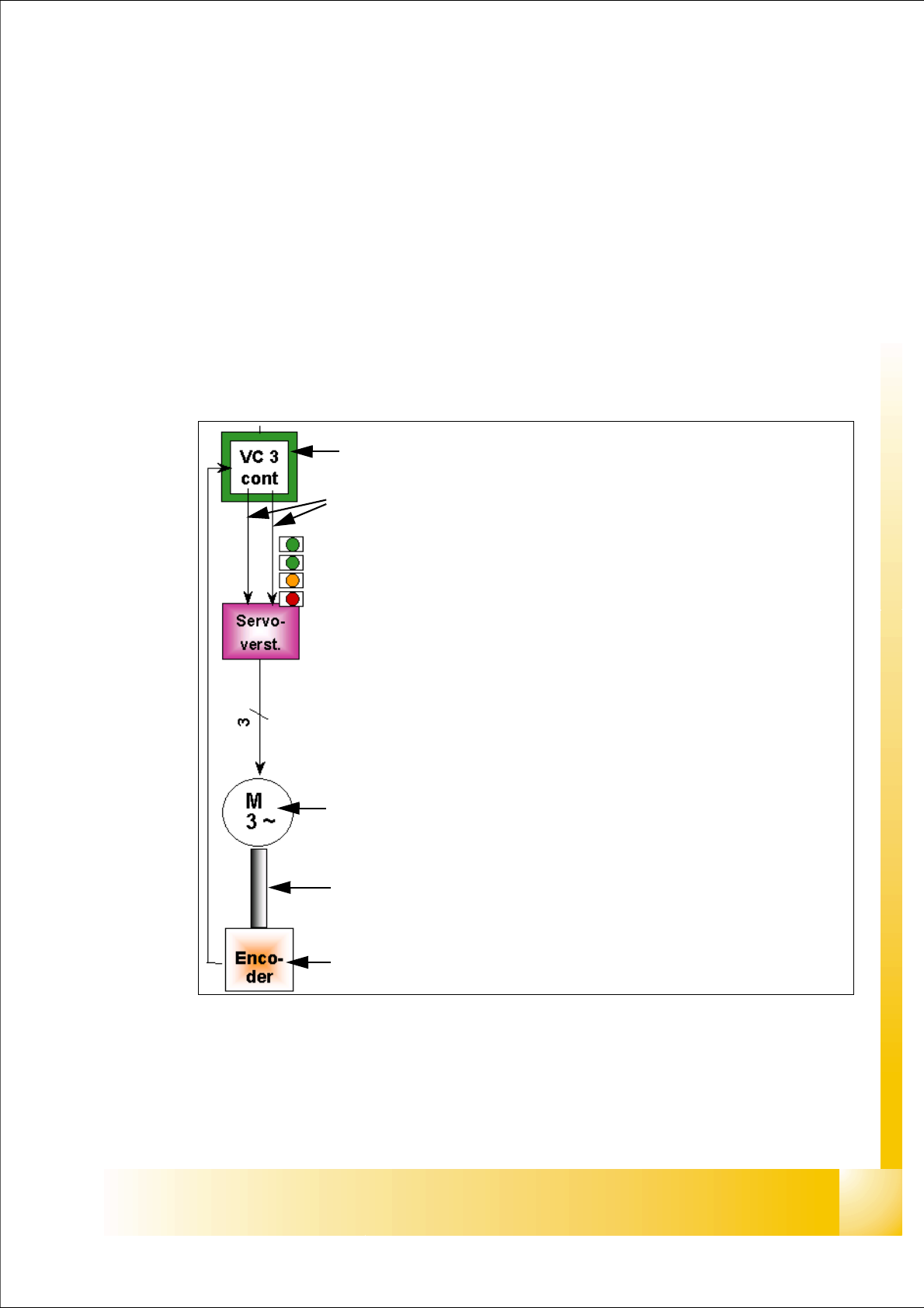
The closed-loop control system for control of the head axes consists of the following parts. Bet-
ween the head axes, some differences which will be explain later in this chapter.
– Axis card with VC 3 Controller (on free axis the VC 3 controller may are missing)
– Servo card (SDS)
– Motor
– Measuring system (Incremental- scale and -encoder)
Fig. 6.3 - 1 Example: Axis control Star axis
Axis card A363 with VC 3 Controller (VC = Velocity Commutation)
Control signals I
nom "W" and I nom "U"
LED‘s on the Servo amplifier:
– Power supply ON
– Servo enable, if the the enable signal from the axis board available.
– Display R.M.S. current limiter shorter than 2,5 s.
– Error: Overvoltage, -current, -temperature or Nominal current-overstep-
ping longer than 2,5 sec.
Servo board control directly the motor.
3 Phase AC motor.
Between the motor and the incremental encoder exist a fixed mechanical
combination.
Incremental encoder: transmit the exact position of the axis via the track
signals.
1 - 36
Student Guide SIPLACE X
6 Collect&Place-Head 20 Edition 09/2005
36
6.3.1.1 Overview positioning time 12 segment C&P head
for completness. 6
6.3.1.2 Overview positioning time 6 segment C&P head
For completness. 6
6.3.1.3 Overview positioning time 20 segment C&P head
6
Attention
If you want to check the axis dynamic on the C&P 20 head z-axis, you have to move the gantry to
the calibration tool pocket.
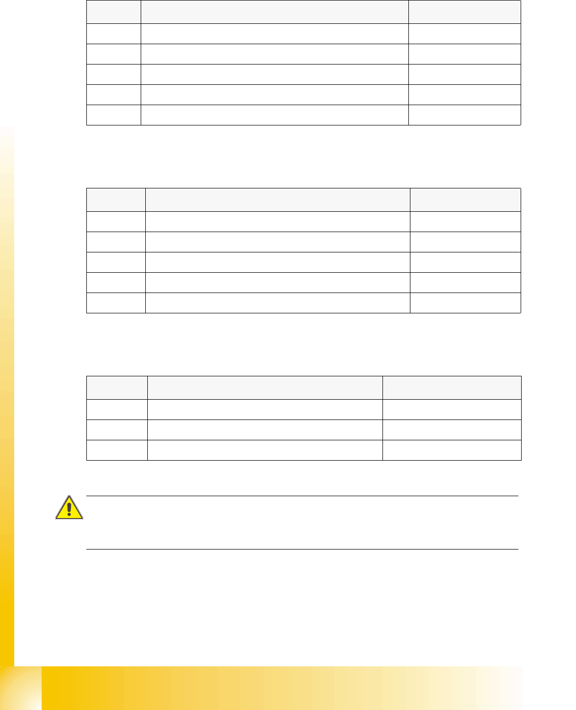
Axis Mode / Distance Positioning time
Star Axis continuous run / 1 Star step 46ms +/-3ms
Z absolute, free space / 685 digits 24ms, -1ms
Z Light barrier bottom, into Calibration tool pocket / ca. 685 digits 24ms +/-3ms
DP 100 digits 13ms +/-3ms
DP 3600 digits 43ms +/-3ms
Table 6.3 - 1 Positioning time 12 segment C&P head DLM2
Axis Mode / Distance Positioning time
Star
Axis continuous run / 1 Star step 70ms +/-3ms
Z absolute, free space / 685 digits 30ms +/-3ms
Z Light barrier bottom, into calibration tool pocket / ca. 685 digits 30ms +/-3ms
DP 200 digits 38ms +/-3ms
DP 7200 digits 85ms +/-3ms
Table 6.3 - 2 Positioning time 6 segment C&P head DLM2
Axis Mode / Distance Positioning time
Star
Axis continuous run / 1 Star step 18° 28,5ms +/-0,5ms
Z absolute, free space / 20000Digits, 10000µm nom. 16ms
DP not controlled from Axis controller ---
Table 6.3 - 3 Positioning time C&P 20 head
1 - 37
Student Guide SIPLACE X
Edition 09/2005 6 Collect&Place-Head 20
37
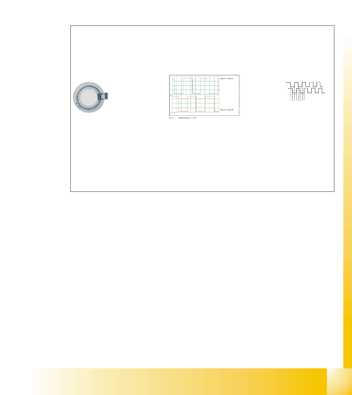
6.3.2 Track signals head axes
The track signals undertake a meaning function in the case of the new drive concept of the HF
machine. They are responsible for the exactly and precise positioning of the axes and are used
as only response of the closed-loop control system so that the track signals have an important
influence on dynamics of the axes.
6.3.2.1 Preparation of the track signals for control the Star axis as example
Track Signal - Star Axis (not adjustable)
Digital Track Signal A, B and N
(zero
pulse) sent to Interm. Distributor Board.
Sensor
3.6 Vpp
Multiplication and Digitalization
of the Analogue
Track Signals A, and B
by
the
Digital Access
Controller on theInterm. Distributor Board.
(Multiplication by a factor of 25 for Digital Conversion)
Rotor
Scale
(3600 ticks / 360° of scale)
Incremental scale on the
DLM 2 C&P head
Transfer the track signals
to the axis board A 363
with VC3
12341234…..
Axis board A 363 with
VC3
Final Multiplication at Control
Unit Axis Decoder
.
(Multiplication by factor of 4)
End Result:
(3600) x (25) x (4) =
360.000 pulses / 360
°
Therefore ....
1° =1000 digit
1 digit = 0.001°