SiplaceX4_en.pdf - 第427页
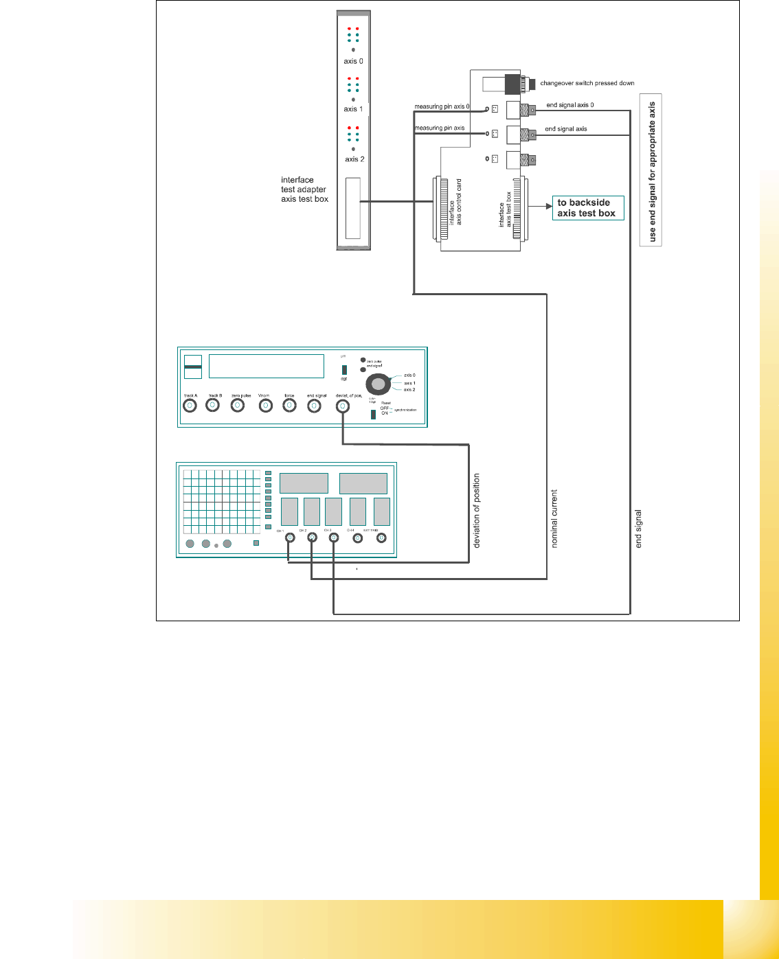
1 - 39 S tudent Guide SIPLACE X Edition 09/2005 6 Collect&Place-Head 20 39 6.3.3.2 T est setup with axis testbox Fig. 6.3 - 3 T est setup to check the dynamic ,Gant ry 11
1 - 38
Student Guide SIPLACE X
6 Collect&Place-Head 20 Edition 09/2005
38
6.3.3 Axis control Star axis
The Star axis is driven with a 3 phase AC stepping motor with an intermediate circuit voltage of
120V. The control of the axis occurred with two control signals of the VC3 (dephasing 120°) con-
troller I
nom "W" and I nom "U". The third phase is calculated automatically.
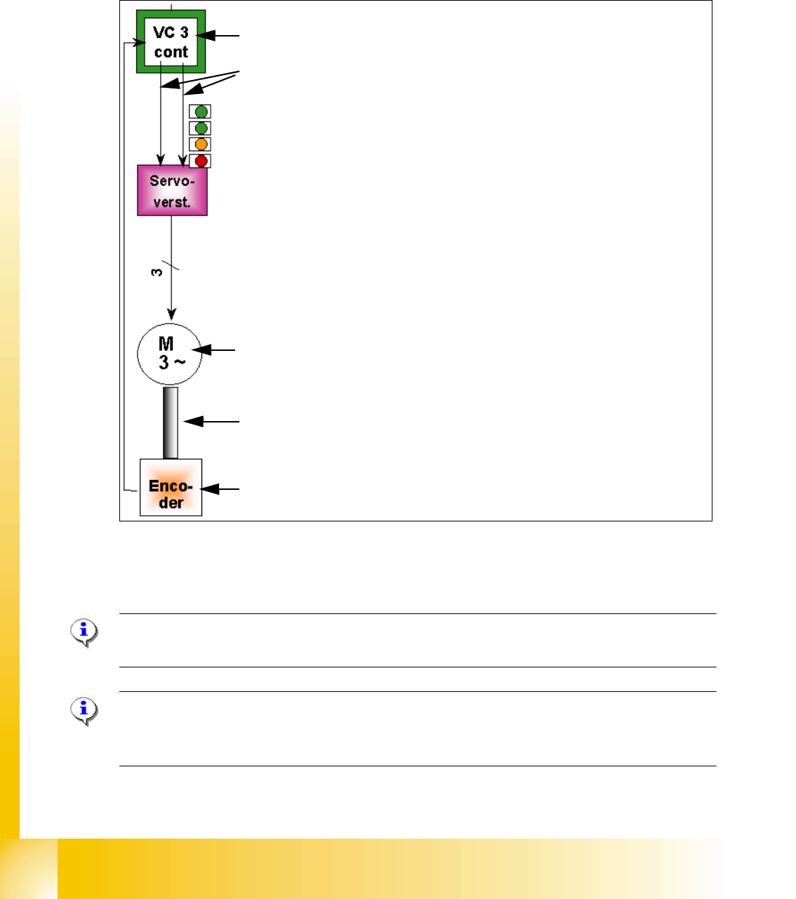
Fig. 6.3 - 2 Axis closed control loop Star axis C&P 6/12/20
6.3.3.1 Check the dynamic Star axis
Please Note:
For detailed notes to check the axis dynamic, please use the "Adjustment manual".
Please Note:
Before adjusting the axes, ensure that the machine has reached its operating temperature.
Switch the machine on at least 30 minutes before you begin work.
Axis card A363 with VC 3 Controller (VC = Velocity Commutation)
Control signals I
nom "W" and I nom "U"
LED‘s on the Servo amplifier:
– Power supply ON
– Servo enable, if the the enable signal from the axis board available.
– Display R.M.S. current limiter shorter than 2,5 s.
– Error: Overvoltage, -current, -temperature or Nominal current-overstep-
ping longer than 2,5 sec.
Servo board control directly the 3 phase AC motor.
3 Phasen AC Motor.
Between the motor and the incremental encoder exist a fixed mechanical
combination.
Incremental encoder: transmit the exact position of the axis via the track
signals.
1 - 40
Student Guide SIPLACE X
6 Collect&Place-Head 20 Edition 09/2005
40
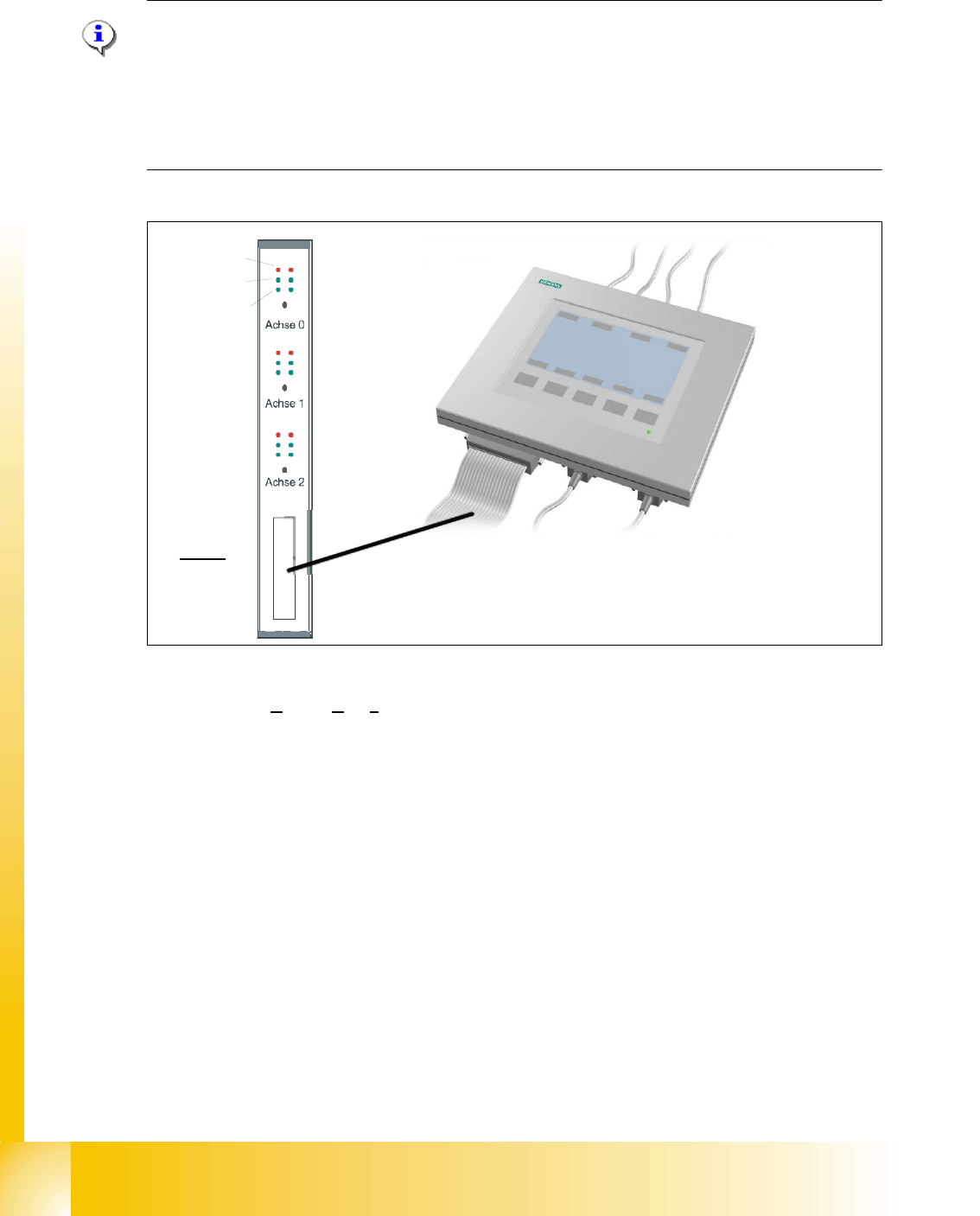
6.3.3.3 Test setup with SAT-Box
Please Note:
-> for dynamic check it may be enough to check positioning time and overshoots of the
axis with the display at SIPLACE Axis Tester and the values from adjustment tables.
-> for troubleshoting the dynamic analysis have to be done with a appropriate oscilloscope
->For further hints checking the dynamics with the aid of the SAT-Box please use the official Ad-
justment manual. 6
Fig. 6.3 - 4 Test set up SAT-Box
Legend outputs Siplace Axis Tester to oscilloscope channels
(1) Nominal speed signal (Vnom)
not connected to the scope at X (HF)
(2) uncommutated nominal current (Vreg)
connect to CH2
(3) Deviation of position connect to CH1 (4) End signal connect to CH 3
Axis unit error
Servo ON
Initialize
Counter error
Zero puls
End signal
Interface:
Test adapter,
Axis test box,
SAT-Box
2
4
1
3