SiplaceX4_en.pdf - 第430页
1 - 42 S tudent Guide SIPLACE X 6 Collect&Place-Head 20 Edition 09/2005 42 6.3.4 Axis control Z-Axis The Z-axis is driven with a DC servo motor . The co ntrol of the axis occurred with one control si- gnals of the VC…
1 - 41
Student Guide SIPLACE X
Edition 09/2005 6 Collect&Place-Head 20
41
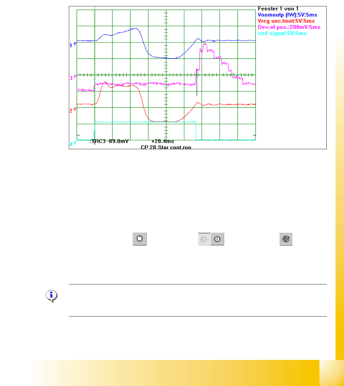
6.3.3.4 Example for dynamic with the control signal of the Vnom. output
The Axis dynamic of the Star axis is checked with Star step continuos run. At Vnominal output of
the Axis tester pass a motor current signal. (Control signal1) The uncommutated nominal current
signal (Signal 3) show the friction of the axis system, here it show NO increased friction.
The positioning time for the C&P 20 Star axis step is 28,5 +/-0,5 ms (31.01.05).
Fig. 6.3 - 5 Dynamic signals Star axis 20 segment C&P head
Legend
SITEST: 6
➠ Select "C&P heads" ==> "Select head" ==>"Axis functions" ==> "Select
Star-axis" ==> "Continuous run Star" ==> Edit: Waiting time "500 ms" ==> "Accept".
➠ If necessary, press the START button.
Please Note:
If the positioning time is to slow or the uncommutated motor current deviate clearly from the signal
above please check the star axis mechanic or electrical components in the control loop. 6
(1) Motor phase current signal on V nom.
output X (HF) machine
(2) Uncommutated Current signal Vreg
(3) Position of deviation (4) End signal
1
2
3
4
1 - 42
Student Guide SIPLACE X
6 Collect&Place-Head 20 Edition 09/2005
42
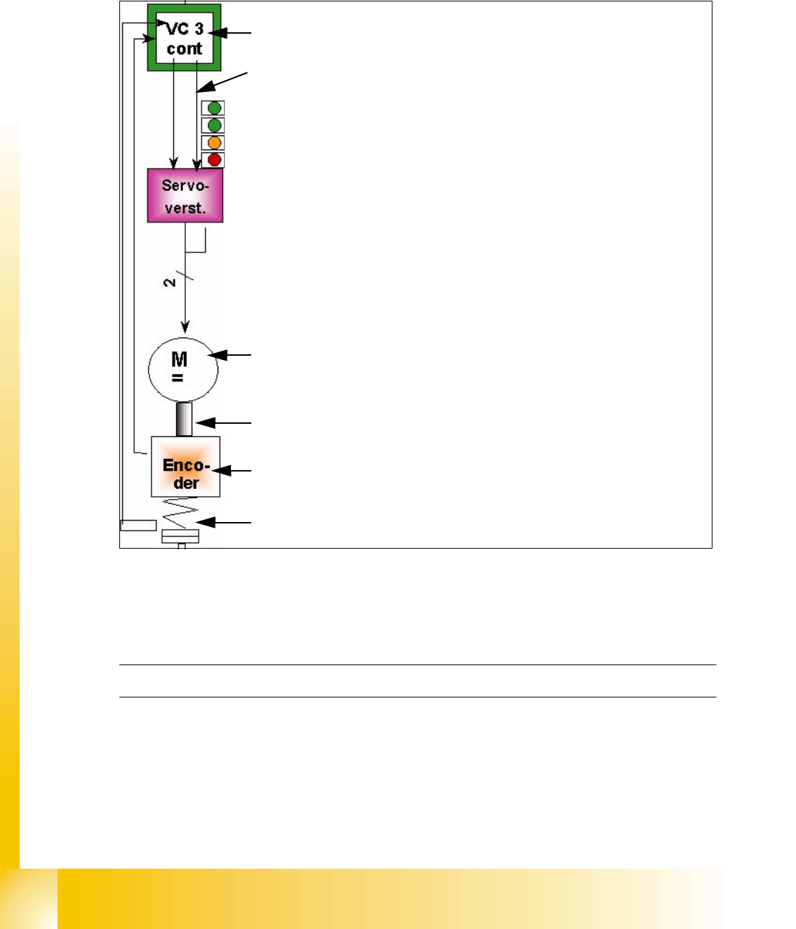
6.3.4 Axis control Z-Axis
The Z-axis is driven with a DC servo motor. The control of the axis occurred with one control si-
gnals of the VC3 controller I
nom "W" and I nom "U" = 0. The intermediate circuit voltages is
approx. 24V.
Fig. 6.3 - 6 Axis control Z-Axis
6.3.4.1 Check the dynamic Z-Axis
6.3.4.2 Test setup
Please Note:The test setup for the Z-Axis is the same as the Star-Axis
The positioning time for the Z-Axis is 30ms +/-3ms (6 segment C&P head) and 24ms, -1 ms of the
12 segment C&P head.
The positioning time C&P 20 for the same 15 mm distance is approx.
20 ms. The nom. distance should be 10mm within approx. 16ms.
– Move the gantry to the calibration tool pocket (Sitest button) and start the dynamic
check.
Axis card A363 with VC 3 Controller (VC = Velocity Commutation)
Control signal I
nom "W"
LED‘s on the Servo amplifier:
– Power supply ON
– Servo enable, if the the enable signal from the axis board available.
– Display R.M.S. current limiter shorter than 2,5 s.
– Error: Overvoltage, -current, -temperature or Nominal current-over-
stepping longer than 2,5 sec.
Servo board control directly the 3~AC (DC) motor.
3 phase (DC C&P6/12) motor.
Between the motor and the incremental encoder exist a fixed mechanical
combination.
Incremental encoder: transmit the exact position of the axis via the track
signals.
Elastic mech. Combination (Belt) and light barrier below, for the fast
recognition of the lower position.
1 - 43
Student Guide SIPLACE X
Edition 09/2005 6 Collect&Place-Head 20
43
SITEST: 6
➠ "Select "C&P heads" ==> "Select head" ==>"Axis functions" ==> "Select
Z-axis" ==> "Continuous run Z-axis" ==> "Select DIGIT for display" ==>"Edit: Target position
20000 digit and Position mode = absolut" ==> "Sart".
➠ If necessary, press the START button.
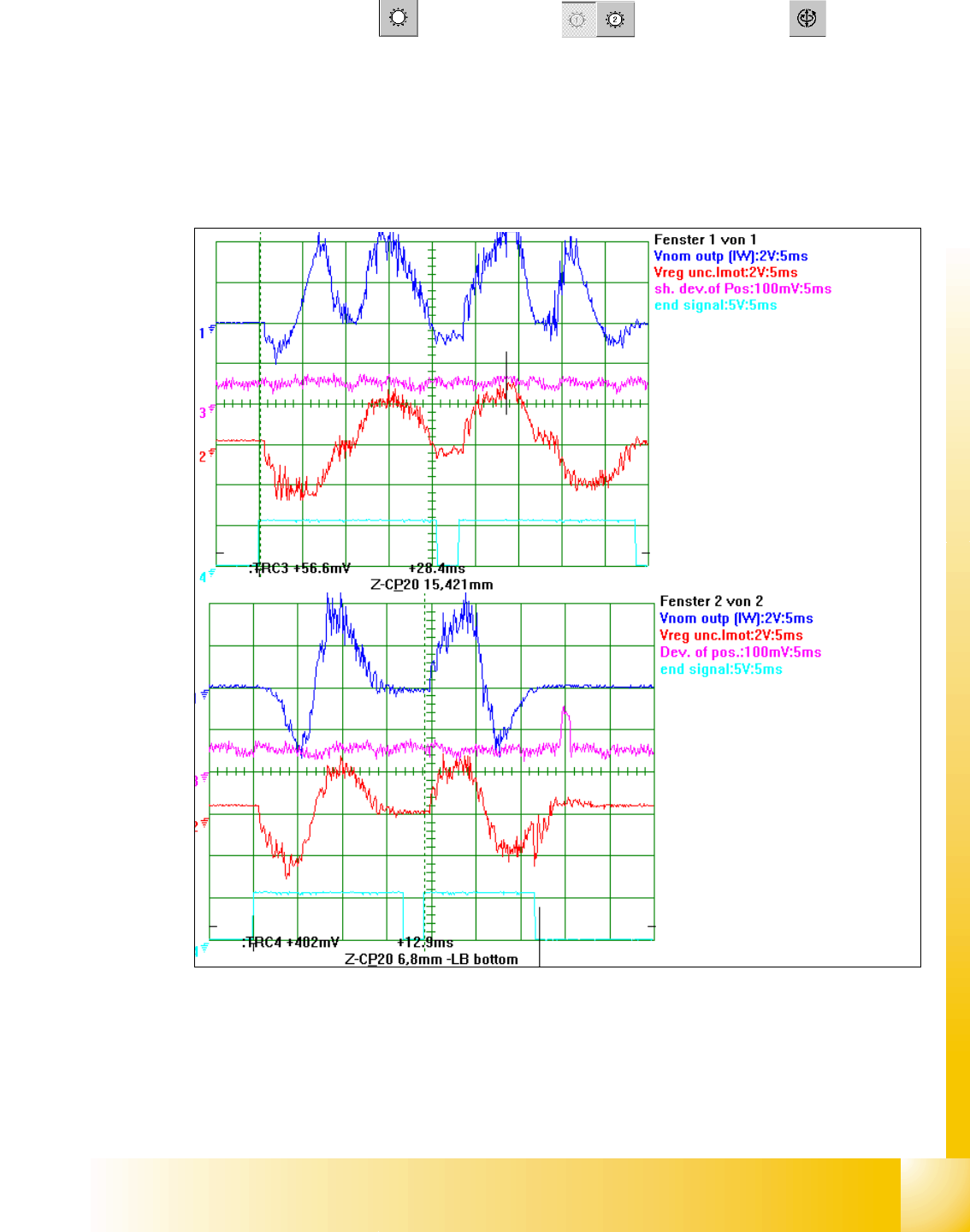
6.3.4.3 Example for C&P 20 Z- axis dynamic with the control signal of the Vnom. output
Fig. 6.3 - 7 Dynamic signals Z-Axis excample 15mm distance / example bottom Z-axis in calibration tool pocket
Legend
(1) Control signal (Axis testbox V nom.) (2) Uncommutated Current signal Vreg
(3) Position of deviation (4) End signal
1
st
Positioning here always up-
wards
2
nd
Positioning here always
downwards.
6,8 mm Positioning with the Z-
Axis into the calibration tool po-
cket.
15,4 mm Positioning with the Z-
Axis into the free space.