SiplaceX4_en.pdf - 第432页
1 - 44 S tudent Guide SIPLACE X 6 Collect&Place-Head 20 Edition 09/2005 44 6.3.5 Axis control DP-Axis The DP axis is driven with a DC servo motor . Th e control of the axis happen a t the integrated DP- control boar …
1 - 43
Student Guide SIPLACE X
Edition 09/2005 6 Collect&Place-Head 20
43
SITEST: 6
➠ "Select "C&P heads" ==> "Select head" ==>"Axis functions" ==> "Select
Z-axis" ==> "Continuous run Z-axis" ==> "Select DIGIT for display" ==>"Edit: Target position
20000 digit and Position mode = absolut" ==> "Sart".
➠ If necessary, press the START button.
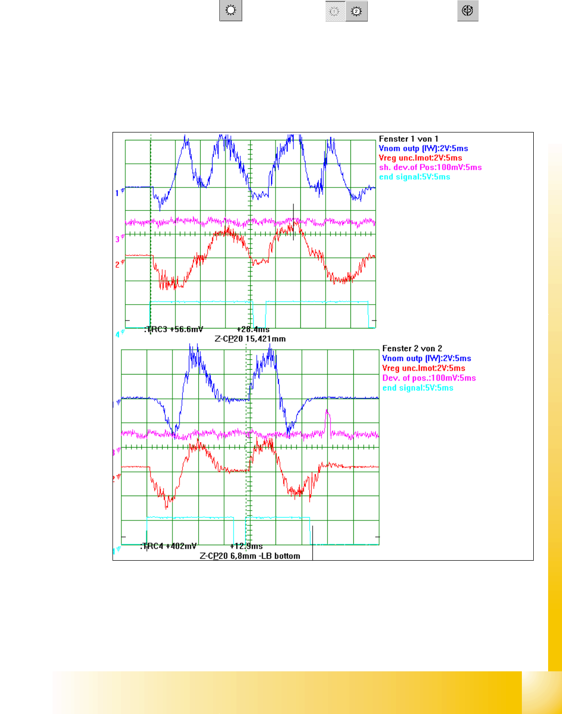
6.3.4.3 Example for C&P 20 Z- axis dynamic with the control signal of the Vnom. output
Fig. 6.3 - 7 Dynamic signals Z-Axis excample 15mm distance / example bottom Z-axis in calibration tool pocket
Legend
(1) Control signal (Axis testbox V nom.) (2) Uncommutated Current signal Vreg
(3) Position of deviation (4) End signal
1
st
Positioning here always up-
wards
2
nd
Positioning here always
downwards.
6,8 mm Positioning with the Z-
Axis into the calibration tool po-
cket.
15,4 mm Positioning with the Z-
Axis into the free space.
1 - 44
Student Guide SIPLACE X
6 Collect&Place-Head 20 Edition 09/2005
44
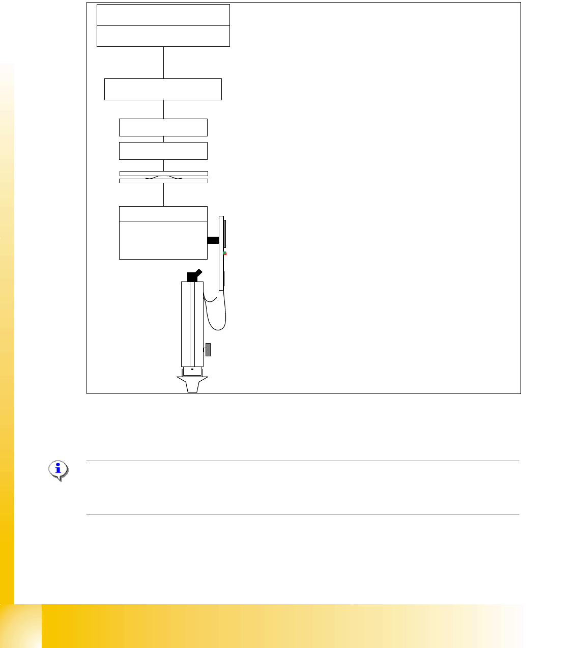
6.3.5 Axis control DP-Axis
The DP axis is driven with a DC servo motor. The control of the axis happen at the integrated DP-
control board connected to DP-mother board.
No stepping motor for swivel in /out is necessary for the C&P20 head.
Fig. 6.3 - 8 Axis control DP-Axis on one segment of the C&P 20 head
6.3.5.1 Check the dynamic DP-Axis
Please Note:
NO test points for the DP-Axis dynamic check are available on C&P 20 head. The on board control
is optimized on the Segement. It is replaced in any kind of error.
MC
head board / TQM module
µP 'DP-tasks'
head adapter
COM board
distributor board
Motherboard
DP-Master
CAN-Bus
head CAN-Bus
E
(nergie)
D (ata)
transformer
(
collector ring)
Fixed
rotary
DP-control board
DP-drive with
Encoder and
Motor
(and Vacuum-air kiss channel)
20 times
The MC transmit the activation commands
with the machinen CAN-Bus to the processor
on the headboard.
The processor activate with 4 DP-Tasks and
the ’head-CAN-Bus system with
>Head adapter,
>distributor board,
> the collector ring of the E/D-translator
to the ’Motherboard with the DP-Master.
The movement / dynamic of the DP-Motors in
the Segment is controlled on the DP-control-
board. Positioncounting pulses came fron an
integrated HALL-Incremental encoder.

Student Guide SIPLACE X
Edition 09/2005 Contents
1
Chapter
Table of Contents
9 Component handling . . . . . . . . . . . . . . . . . . . . . . . . . . . . . . . . . . . . . . . . . . . . . . . . 3
9.1 Overview . . . . . . . . . . . . . . . . . . . . . . . . . . . . . . . . . . . . . . . . . . . . . . . . . . . . . . . . . . . . . . . . . . . . . . . 3
9.1.1 Component changeover table (COT) S- table . . . . . . . . . . . . . . . . . . . . . . . . . . . . . . . 4
9.1.2 Component changeover table (COT) (X- table). . . . . . . . . . . . . . . . . . . . . . . . . . . . . . 6
9.1.3 Pneumatic tape cutter and empty tape duct . . . . . . . . . . . . . . . . . . . . . . . . . . . . . . . . 8
9.2 Component changeover table . . . . . . . . . . . . . . . . . . . . . . . . . . . . . . . . . . . . . . . . . . . . . . . . . . . . . 9
9.2.1 Structure of the component table (S- table). . . . . . . . . . . . . . . . . . . . . . . . . . . . . . . . . 9
9.2.2 Structure of the component table (X- table). . . . . . . . . . . . . . . . . . . . . . . . . . . . . . . . 10
9.2.3 Function description of the component changeover table. . . . . . . . . . . . . . . . . . . . . 11
9.2.3.1 Docking . . . . . . . . . . . . . . . . . . . . . . . . . . . . . . . . . . . . . . . . . . . . . . . . . . . . . . . 11
9.2.3.2 Undocking . . . . . . . . . . . . . . . . . . . . . . . . . . . . . . . . . . . . . . . . . . . . . . . . . . . . . 11
9.2.3.3 Adjustment pneumatic cylinder. . . . . . . . . . . . . . . . . . . . . . . . . . . . . . . . . . . . . . 12
9.2.3.4 Position of the docking unit in the machine . . . . . . . . . . . . . . . . . . . . . . . . . . . . 12
9.2.3.5 Mounting of Docking unit . . . . . . . . . . . . . . . . . . . . . . . . . . . . . . . . . . . . . . . . . . 14
9.2.4 Adjustment the COT height . . . . . . . . . . . . . . . . . . . . . . . . . . . . . . . . . . . . . . . . . . . . 15
9.2.5 Optionally extension on the COT. . . . . . . . . . . . . . . . . . . . . . . . . . . . . . . . . . . . . . . . 16
9.2.5.1 Tape reel holder for the 3th reel at the 3x8mm S-Feeder . . . . . . . . . . . . . . . . . 16
9.2.5.2 Additional reel holder of the X- table . . . . . . . . . . . . . . . . . . . . . . . . . . . . . . . . . 16
9.2.5.3 Compressed air supply for Bulkcase feeder. . . . . . . . . . . . . . . . . . . . . . . . . . . . 17
9.2.5.4 Additional feeder fixation . . . . . . . . . . . . . . . . . . . . . . . . . . . . . . . . . . . . . . . . . . 18
9.2.5.5 Additional Communication unit for splice detection . . . . . . . . . . . . . . . . . . . . . . 18
9.3 X- Feeder. . . . . . . . . . . . . . . . . . . . . . . . . . . . . . . . . . . . . . . . . . . . . . . . . . . . . . . . . . . . . . . . . . . . . . 19
9.3.1 General . . . . . . . . . . . . . . . . . . . . . . . . . . . . . . . . . . . . . . . . . . . . . . . . . . . . . . . . . . . 19
9.3.2 Parts of the X- Feeder (front view) . . . . . . . . . . . . . . . . . . . . . . . . . . . . . . . . . . . . . . 20
9.3.3 Parts of the X- Feeder (back view) . . . . . . . . . . . . . . . . . . . . . . . . . . . . . . . . . . . . . . 21
9.3.4 Overview feeder types. . . . . . . . . . . . . . . . . . . . . . . . . . . . . . . . . . . . . . . . . . . . . . . . 22
9.3.5 Track width for the feeder types . . . . . . . . . . . . . . . . . . . . . . . . . . . . . . . . . . . . . . . . 22
9.3.6 Contactless Power- and Data- Interface . . . . . . . . . . . . . . . . . . . . . . . . . . . . . . . . . . 23
9.3.7 Adjustable steps on the X- feeder . . . . . . . . . . . . . . . . . . . . . . . . . . . . . . . . . . . . . . . 23
9.3.8 4 Pick up positions 8mm X- Feeder. . . . . . . . . . . . . . . . . . . . . . . . . . . . . . . . . . . . . . 24
9.3.9 3 Pick up positions 12mm X- Feeder. . . . . . . . . . . . . . . . . . . . . . . . . . . . . . . . . . . . . 24
9.3.10 One pick up position in all other X- Feeder . . . . . . . . . . . . . . . . . . . . . . . . . . . . . . . 24
9.3.11 X- Feeder operator panel . . . . . . . . . . . . . . . . . . . . . . . . . . . . . . . . . . . . . . . . . . . . 25
9.3.12 Settings and function in the Main Menu X- Förderer. . . . . . . . . . . . . . . . . . . . . . . . 26
9.3.12.1 Sequence in the 8mm X-feeder main menu. . . . . . . . . . . . . . . . . . . . . . . . . . . 27
9.3.12.2 Sequence in the 12mm X-feeder main menu. . . . . . . . . . . . . . . . . . . . . . . . . . 27
9.3.12.3 Adjustments of the Pick up position only on 8mm X- Feeder. . . . . . . . . . . . . . 28