SiplaceX4_en.pdf - 第435页
1 - 3 S tudent Guide SIPLACE X Edition 09/2005 9 Co mponent handling 3 9 Component handling 9.1 Overview These chapte r includes the topics o f component chang eover table (COT) the relevant docking unit and the pneumati…

1 - 2
Student Guide SIPLACE X
Contents Edition 09/2005
2
9.3.12.4 Menu pick up position manual in the main menu . . . . . . . . . . . . . . . . . . . . . . . 28
9.3.12.5 Menu Pitch in the main menu . . . . . . . . . . . . . . . . . . . . . . . . . . . . . . . . . . . . . . 29
9.3.12.6 Menu transport speed in the main menu . . . . . . . . . . . . . . . . . . . . . . . . . . . . . 29
9.3.12.7 Data menu . . . . . . . . . . . . . . . . . . . . . . . . . . . . . . . . . . . . . . . . . . . . . . . . . . . . 30
9.3.13 Activation and function in the Service technician menu. . . . . . . . . . . . . . . . . . . . . . 31
9.3.14 Error messages on X-feeder . . . . . . . . . . . . . . . . . . . . . . . . . . . . . . . . . . . . . . . . . . 32
9.4 Pneumatic tape cutter . . . . . . . . . . . . . . . . . . . . . . . . . . . . . . . . . . . . . . . . . . . . . . . . . . . . . . . . . . . 33
9.4.1 Structure and function of the pneumatic tape cutter . . . . . . . . . . . . . . . . . . . . . . . . . 33
9.4.2 Jumper setting on the control unit at the tape cutter . . . . . . . . . . . . . . . . . . . . . . . . . 35
9.4.3 Empty tape duct. . . . . . . . . . . . . . . . . . . . . . . . . . . . . . . . . . . . . . . . . . . . . . . . . . . . . 36
1 - 3
Student Guide SIPLACE X
Edition 09/2005 9 Component handling
3
9 Component handling
9.1 Overview
These chapter includes the topics of component changeover table (COT) the relevant docking unit
and the pneumatic tape cutter.
Four moveable component changeover tables could be docking on the X-machine. On location 2
and/or 4 on the X- series the MTC 2 can be set up or retrofitted as an option. The component
changeover tables can be "dock" or "undock" by activation of one button (electrical and mechan-
ical connection).
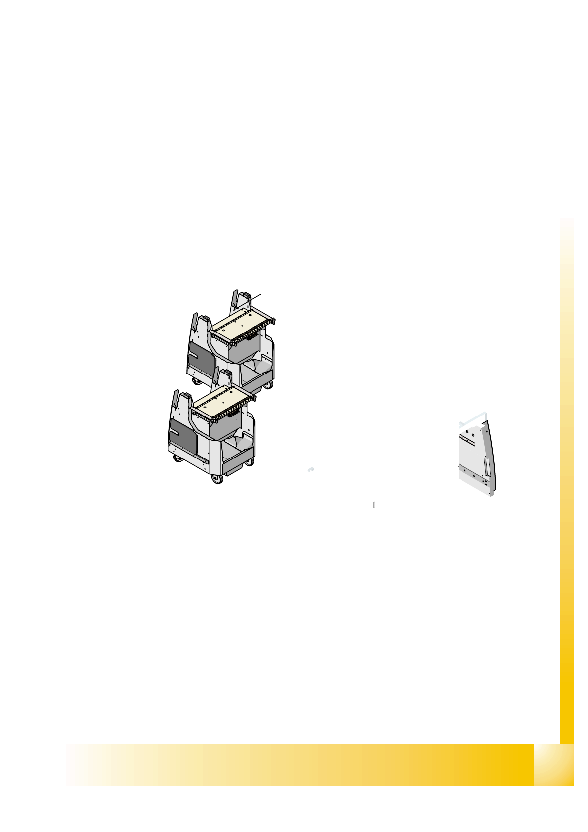
Fig. 9.1 - 1 Shows the buttons for docking and undocking the COT‘s
1. Button(1) for docking and undocking the COT for machine with one hand operation.
1 - 4
Student Guide SIPLACE X
9 Component handling Edition 09/2005
4
9.1.1 Component changeover table (COT) S- table
The component handling unit consist of the COT and the docking unit with tape cutter.
S- table : 9
Technical Data component table: 9
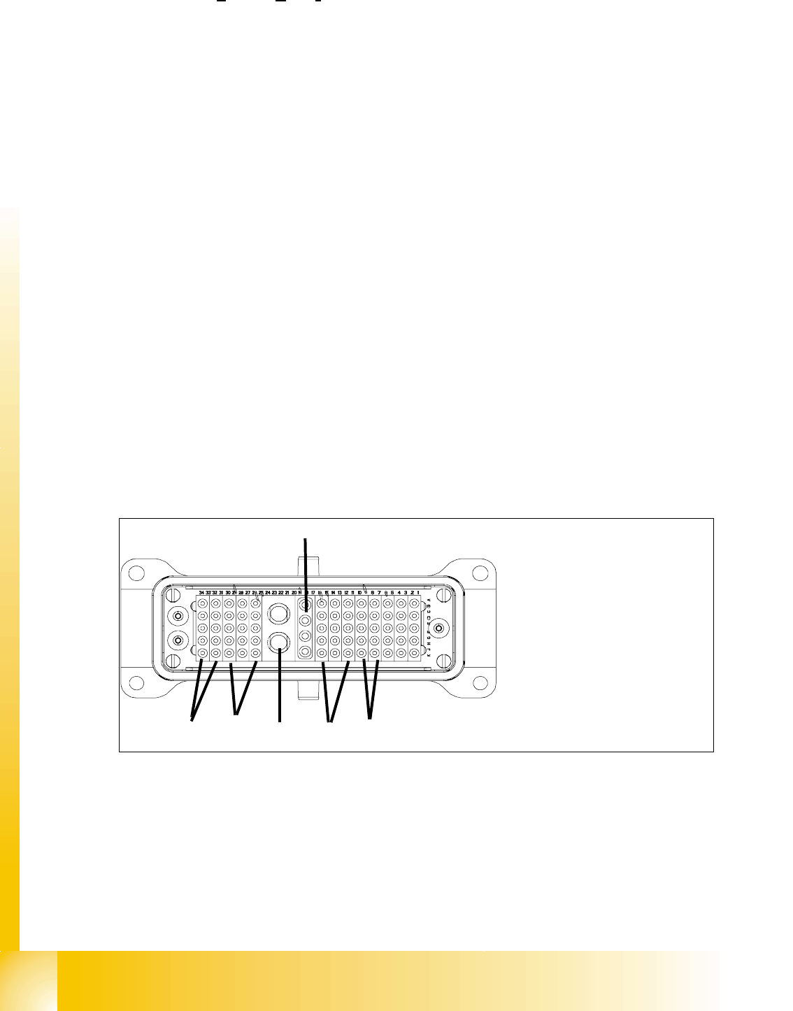
Connection the COT to the machine 9
Fig. 9.1 - 2 ODU Connector for COT
Feeder capacity
180 tracks width 8mm (3x8mm S feeder)
120 tracks width 8mm (2x8mm S feeder)
Location
4 Component tables with the integrated tape waste container
15 tracks via 30mm for each component table or up to 2 matrix tray changer
undocking
with electric and pneumatic supply or completely manuell when machine is OFF
docking
only with electric and pneumatic supply
Feeder types
Tapes, Bulkcase, Linear magazin, Siplace S-Feeder(F4,F5,S-20,S-
23,S25HM,S27HM,HS50,HS50+,HS60), OEM Feeder, Surftape feeder (8, 12,
16, 24 mm), manual Trays
Interface to the machine
automatically connection if docking the COT
- connect to Power - connect to CAN Bus
- connect to Safety loop - connect to pneumatic air
- connect to the option Splice detection
Component table height
depend from the machine height: Freely adjustable on following SMEMA heights
830 mm ± 15 mm (Standard) 900 mm ± 15 mm (SMEMA)
930 mm ± 15 mm (SMEMA) 950 mm ± 15 mm (SMEMA)
1. Power
2. Safety loop
3. Signaling
4. Compressed air Bulk Case
5. Splice detection
6. CAN Bus
(4)
(5)
(2)
(1)
(3)
(6)