SiplaceX4_en.pdf - 第439页
1 - 7 S tudent Guide SIPLACE X Edition 09/2005 9 Co mponent handling 7 COT with One -Hand Opera tion (X- t able) 9 For the docking process, push the component change over table into the docking unit as much as possible, …

1 - 6
Student Guide SIPLACE X
9 Component handling Edition 09/2005
6
9.1.2 Component changeover table (COT) (X- table)
The component handling unit consist of the COT and the docking unit with tape cutter.
If a C&P20 head is installed a X- table has to be placed.
X- table : 9
Technical Data component table: 9
Feeder capacity
160 tracks width 8mm, 8mm X - feeder
80 tracks width 12mm, 12mm X- feeder
64 tracks width 16mm, 16mm X- feeder
64 tracks width 24mm, 24mm X- feeder
40 tracks width 32mm, 32mm X- feeder
32 tracks width 44mm, 44mm X- feeder
24 tracks width 56mm, 56mm X- feeder
20 tracks width 72mm, 72mm X- feeder
16 tracks width 88mm, 88mm X- feeder
Location
4 Component tables with the integrated tape waste container
40 tracks à 8mm X- feeder for each component table or up to 2 matrix tray
changer instead of COT
X2: 2 MTC
X3: 1 MTC
undocking
with electric and pneumatic supply or completely manuell when machine is OFF
docking
only with electric and pneumatic supply
Feeder types
Tapes
Interface to the machine
automatically connection if docking the COT
- connect to Power - connect to CAN Bus
- connect to Safety loop - connect to pneumatic air
Component table height
depend from the machine height: Freely adjustable on following SMEMA heights
830 mm ± 15 mm (Standard) 900 mm ± 15 mm (SMEMA)
930 mm ± 15 mm (SMEMA) 950 mm ± 15 mm (SMEMA)
1 - 7
Student Guide SIPLACE X
Edition 09/2005 9 Component handling
7
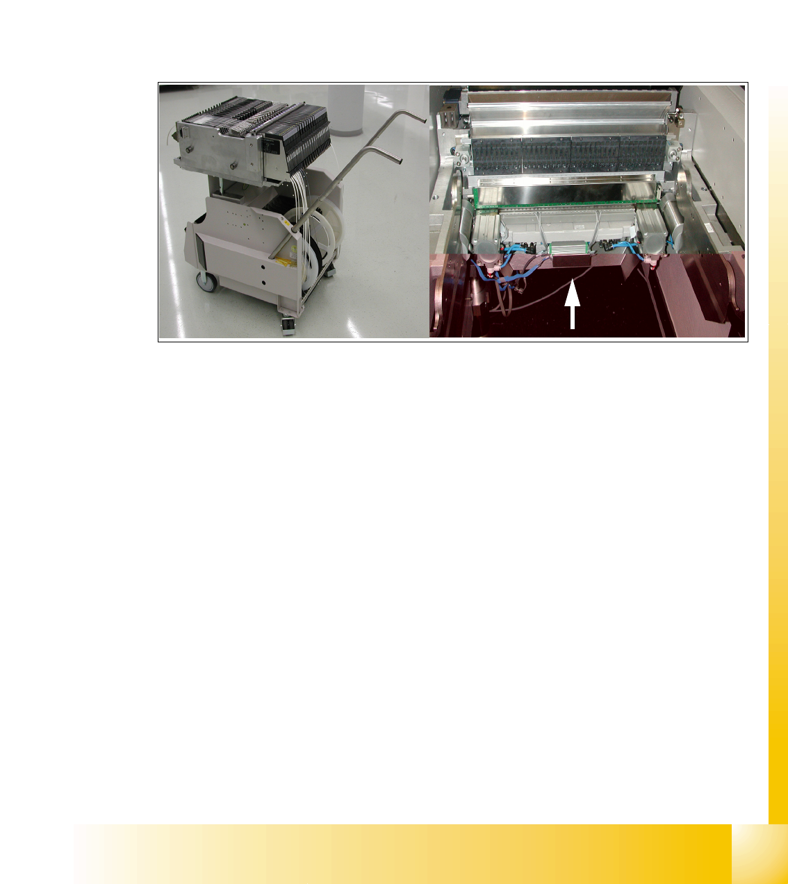
COT with One -Hand Operation (X- table) 9
For the docking process, push the component changeover table into the docking unit as much as
possible, the safety cover have to be be closed. Press button (1) (see Fig. 10.1 - 1) and the COT
is mounted to the machine like described before.
For the undocking process, open the safety cover at the respective area and press button 1 (see
Fig. 10.1 - 1). Now the COT move out like described before.
In case of service if the machine is switched off, the component changeover table can be un-
docked if you push constantly on both sides of the COT.
Fig. 9.1 - 4 COT (X- table) with the docking unit
1 - 8
Student Guide SIPLACE X
9 Component handling Edition 09/2005
8
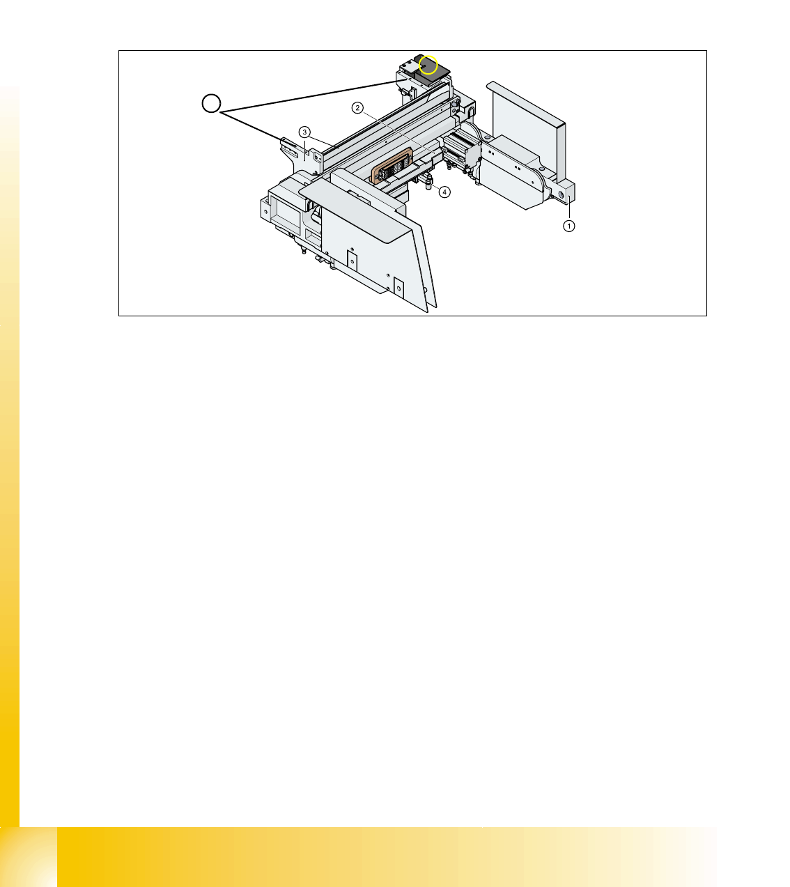
9.1.3 Pneumatic tape cutter and empty tape duct
The pneumatic tape cutter unit is fixed to the frame of the docking unit with 4 screws. It cuts plastic,
aluminum and paper tapes up to a maximum pocket depth of 25 mm. The waste tape fall via the
tape waste chute into the tape waste container below the component table. The empty tape duct
is constructed, that the cutting edges of the tape cutter is covered (Safety), the empty tape duct
has an integrated reject box and mounting suface for nozzle changers of 6 or12 nozzle C&P head
or Twin head.
Fig. 9.1 - 5 Complete docking unit
1. Frame docking unit 2. Pneumatic tape cutter
3. Empty tape duct 4. Electrically and pneumatically connector to the machine
5. Support for the nozzle changer (6) Component reject box for C&P-head
5
6