SiplaceX4_en.pdf - 第44页
1 - 20 S tudent Guide SIPLACE X 2 Overview Edition 09/2005 20 2.2.6 Component changeover t ables A new feeder ge neration has be en develope d for the Siplace X. The se new feeder s also require a new component t able. T…
1 - 19
Student Guide SIPLACE X
Edition 09/2005 2 Overview
19
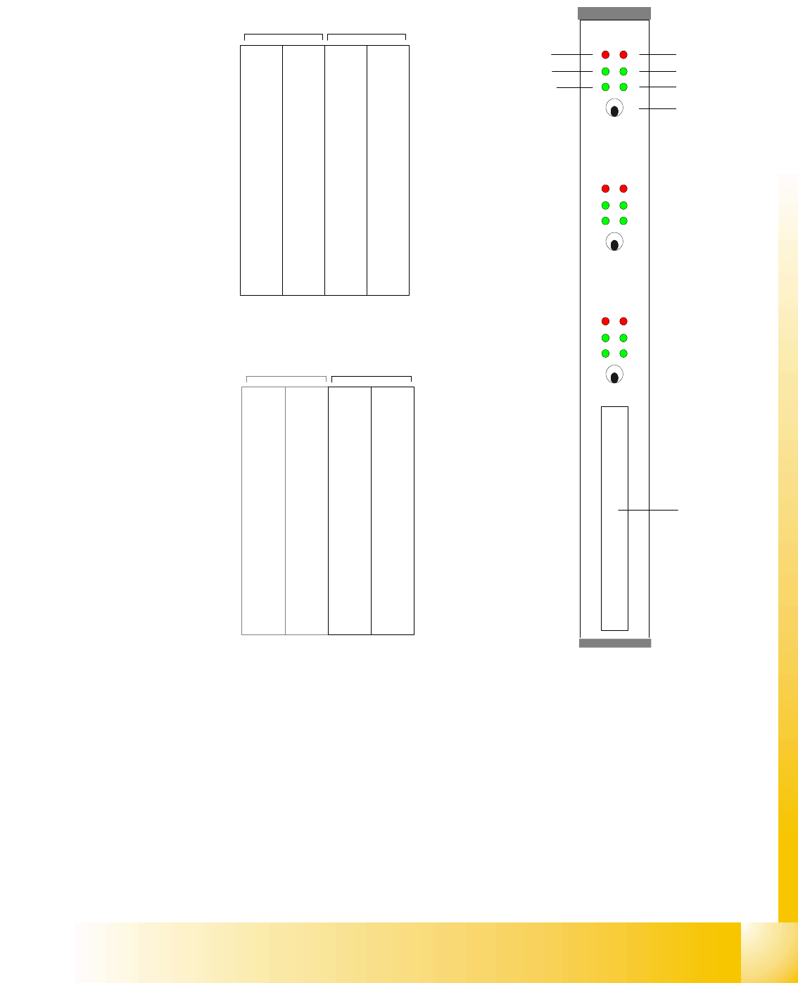
2.2.5.4 Axis Card A363
Abbreviation:
X = X-axis and gantry number
Z1= Z-axis for twin head module 1
Y= Y-axis and gantry number D
1= Rotary axis for twin head modules 1
S= Star axis and gantry number for C&P head Z
2= Z-axis for twin head module 2
Z= Z-axis and gantry number for C&P head D
2= Rotary axis for twin head module 2
DP= Swivel axis and gantry number for C&P
head
The DP/D-axis controller is not used in C&P20
heads.
Counter error
Zero puls
End signal
Common error,
Board error
Initialisation
Servo On
Axis switch off/on
Axis 0
Axis 1
Axis 2
Interface
Axis test box
X 1
Address
0
Y 1
Address
1
S 1
Address
2
Z 1
Address
3
DP 1
Address
5
free
Address
5
X 4
Address
6
Y 4
Address
7
S 4
Address
8
Z 4
Adress
9
DP 4
Address
10
free
Address
11
Gantry 1 Gantry 4
Placement area PA 1
Servos 'bottom'Servos 'top'
X 2
Address
16
Y 2
Address
17
S 2
Address
18
Z 2
Address
19
DP 2
Address
20
free
Address
21
X 3
Address
22
Y 3
Address
23
S3/Z
2
Address
24
Z/Z
1
Address
25
DP/D
1
Address
26
/D
2
Addres
27
Gantry 2 not used Gantry 3
Placement area PA 2
Servos 'bottom'Servos 'top'
1 - 20
Student Guide SIPLACE X
2 Overview Edition 09/2005
20
2.2.6 Component changeover tables
A new feeder generation has been developed for the Siplace X. These new feeders also require
a new component table. The new table has no electronic assemblies. The conventional compo-
nent table uses the communication unit for feeder supply and control. The power supply to the
feeders is now non-contacting, run via an inductive interface at the docking unit, directly to the
feeders. The control and communication between the feeder control unit (FCU) and the feeders
is conducted via two optoelectronic channels (fiber optics). The FCU is connected to the machine
control unit via the machine CAN Bus. Both S-tables and X-tables can be used with the machine.
Restriction: If the machine has C&P20 heads, only X-tables may be used.
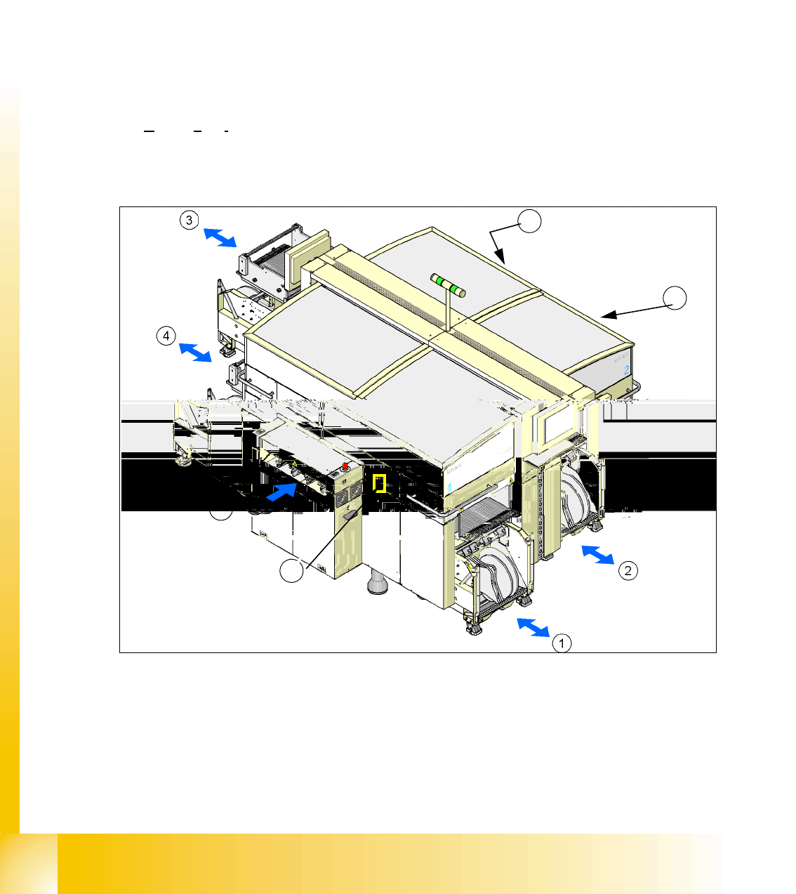
2.2.6.1 Docking and Undocking
The changeover table (COT) is automatically docked and undocked to/from the machine via 2
pneumatic cylinders. To dock the COT, move the table to the docking unit, close the cover and
press button 5. To undock the COT, open the cover and press button 5.
.
Fig. 2.2 - 8 Shows the buttons for docking and undocking the COTs
(1-4) Component table location 1 - location 4
(T) Direction of transport
(5) Button to dock and undock component changeover tables
5
5
5
5
1 - 21
Student Guide SIPLACE X
Edition 09/2005 2 Overview
21
Each S-table has fifteen slots for 8 mm SIPLACE feeders.
This amounts to a total capacity of 180 tracks for 8mm tapes, if 4 component tables are used.
Each X-table has 40 slots for 8mm X-feeders, amounting to a total capacity of 160 individual
tracks, if 4 component tables are used
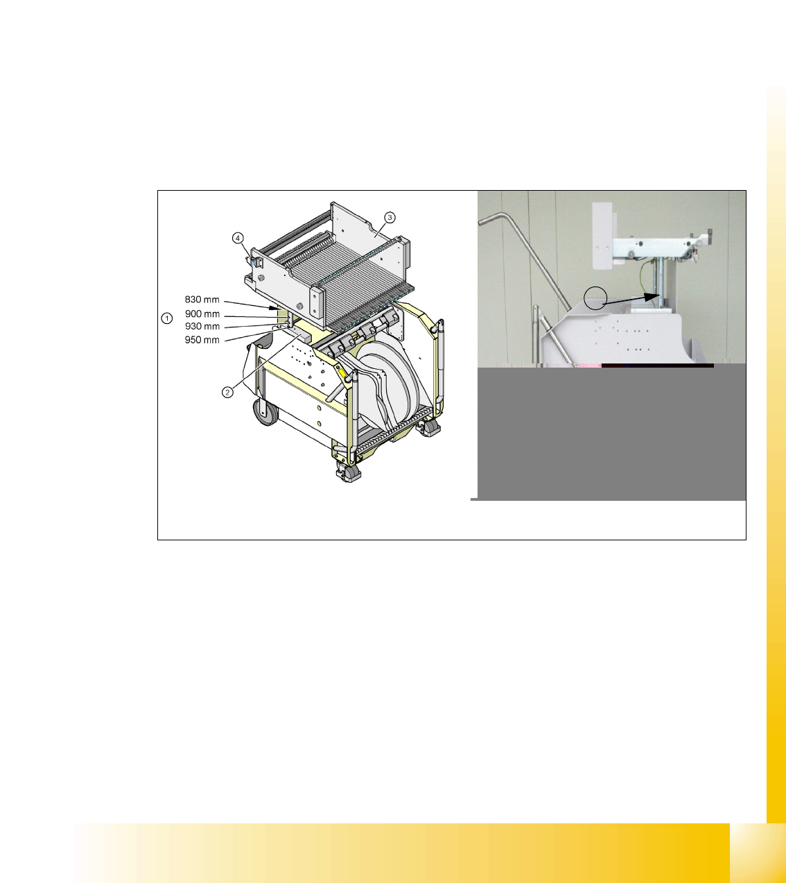
2.2.6.2 Adjusting the Changeover Table Height
The COT can be manually adjusted for the following PCB transportation heights.
Adjustment of S-tables and X-tables is identical.
– 830 mm ± 15 mm standard height
– 900 mm ± 15 mm SMEMA height
– 930 mm ± 15 mm SMEMA height
– 950 mm ± 15 mm SMEMA height
Fig. 2.2 - 9 COT for X-feeder COT for S-feeder
(1) Holes drilled for the various PCB transport heights. adjustment is via insertion of a split pin.
(2) Contact surface (block) for upper part of table
(3) Component table
(4) Reed switch to close the safety circuit to the docking unit
1
Component table for X feeder
Component table for S feeder