SiplaceX4_en.pdf - 第441页
1 - 9 S tudent Guide SIPLACE X Edition 09/2005 9 Component handling 9 9.2 Component changeover t able 9.2.1 Structure of the component t able (S- table) Fig. 9.2 - 1 Component changeover table side view (S- table) 1. Mov…
1 - 8
Student Guide SIPLACE X
9 Component handling Edition 09/2005
8
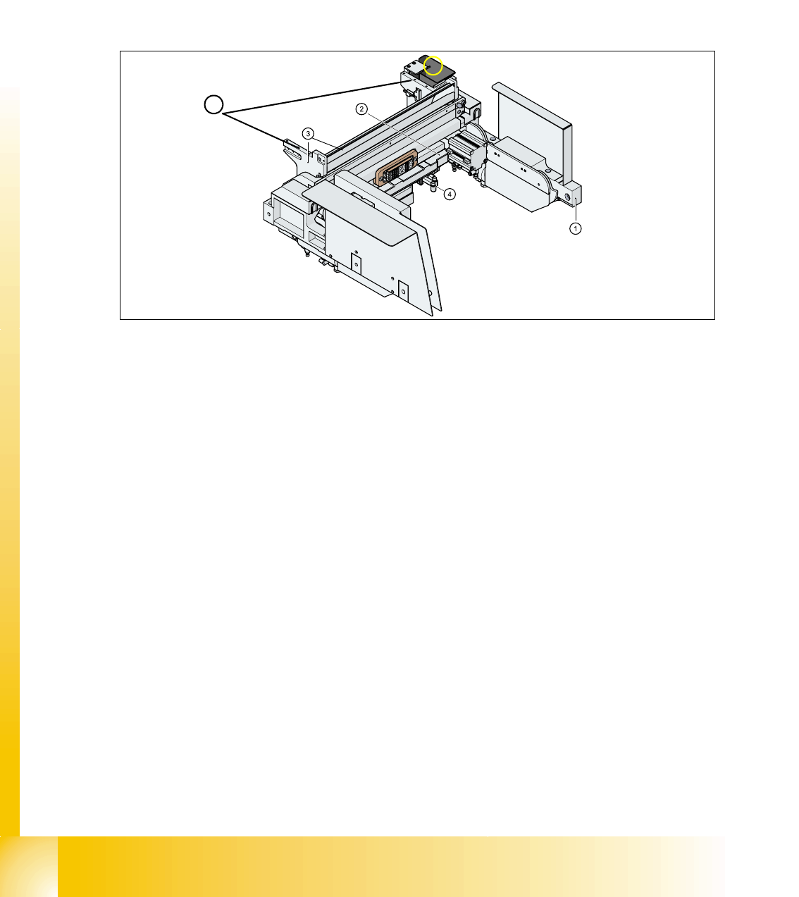
9.1.3 Pneumatic tape cutter and empty tape duct
The pneumatic tape cutter unit is fixed to the frame of the docking unit with 4 screws. It cuts plastic,
aluminum and paper tapes up to a maximum pocket depth of 25 mm. The waste tape fall via the
tape waste chute into the tape waste container below the component table. The empty tape duct
is constructed, that the cutting edges of the tape cutter is covered (Safety), the empty tape duct
has an integrated reject box and mounting suface for nozzle changers of 6 or12 nozzle C&P head
or Twin head.
Fig. 9.1 - 5 Complete docking unit
1. Frame docking unit 2. Pneumatic tape cutter
3. Empty tape duct 4. Electrically and pneumatically connector to the machine
5. Support for the nozzle changer (6) Component reject box for C&P-head
5
6
1 - 9
Student Guide SIPLACE X
Edition 09/2005 9 Component handling
9
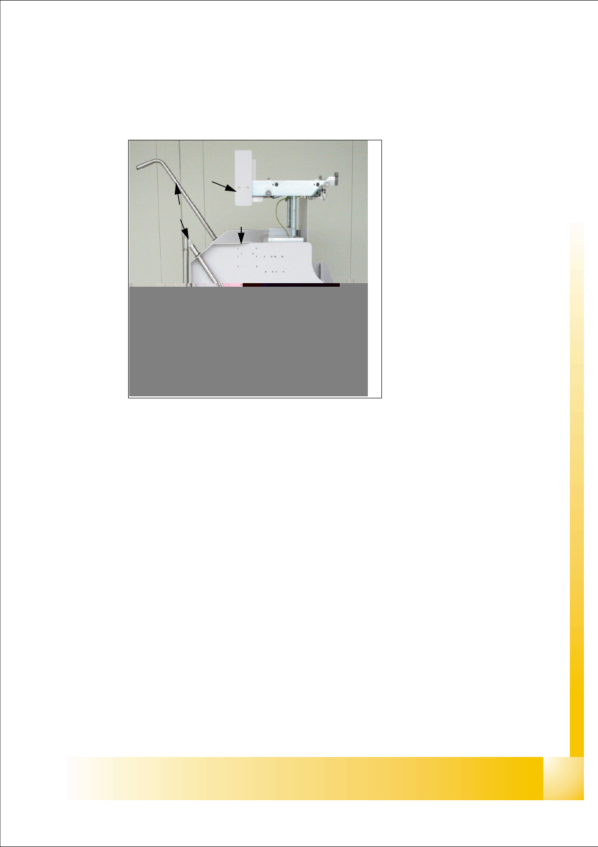
9.2 Component changeover table
9.2.1 Structure of the component table (S- table)
Fig. 9.2 - 1 Component changeover table side view (S- table)
1. Moveable base
2. Feeder table plate
3. Communication unit;option splice detection unit is additional mounted below the communica-
tion unit
LED-Display Communication unit:
RED (Left) - Reset Communication unit
GREEN (Center) - Display Power supply --> OK
Yellow (Right) - Logic OK ( from Version-03:
Standard OFF, it flashes in the case
of the download of the firmware
4. Tape reels container
5. Tape waste container
6. Interface power supply, communication, safety loop
7. Sticker with an Identification number as alphanumeric Signs and as an barcode
8. Handles (for model 2 seperate to swifel)
9. Slot for set up lists on both sides
(1)
(8)
(3)
(4)
(5)
(5)
(2)
(6)
(9)
1 - 10
Student Guide SIPLACE X
9 Component handling Edition 09/2005
10
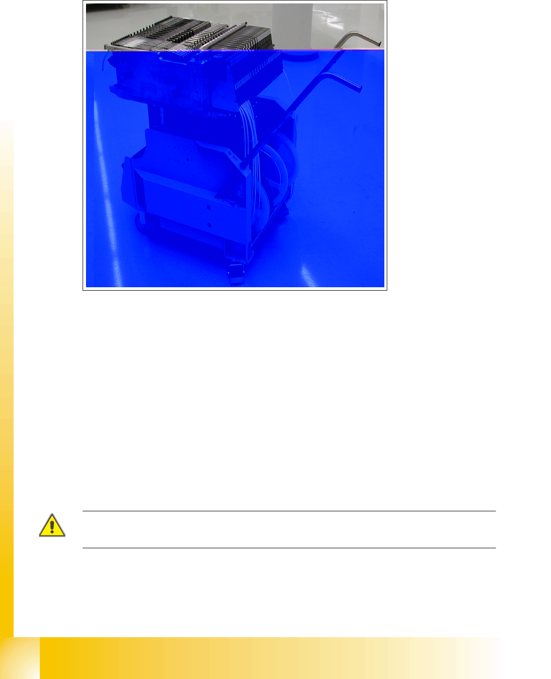
9.2.2 Structure of the component table (X- table)
Fig. 9.2 - 2 COT (X- table) - side view
1. Moveable base
2. Feeder table plate
3. Tape reels container
4. Tape waste container
5. Interface power supply, communication, safety loop
6. Sticker with an Identification number as alphanumeric Signs and as an barcode
7. Handles (for model 2 seperate to swifel)
– Slot for set up lists could be placed on both sides
ATTENTION :
Tracks which are not used has to be filled up with dummy feeder.
(1)
(2)
(3)
(4)
(4)
(5)
(6)
(7)
(7)