SiplaceX4_en.pdf - 第464页
1 - 32 S tudent Guide SIPLACE X 9 Component handling Edition 09/2005 32 9.3.14 Error messages on X-feeder Fig. 9.3 - 20 Error messages Ready for Op eration shows the green LE D-Display, Warning and Error messag es shows …
1 - 31
Student Guide SIPLACE X
Edition 09/2005 9 Component handling
31
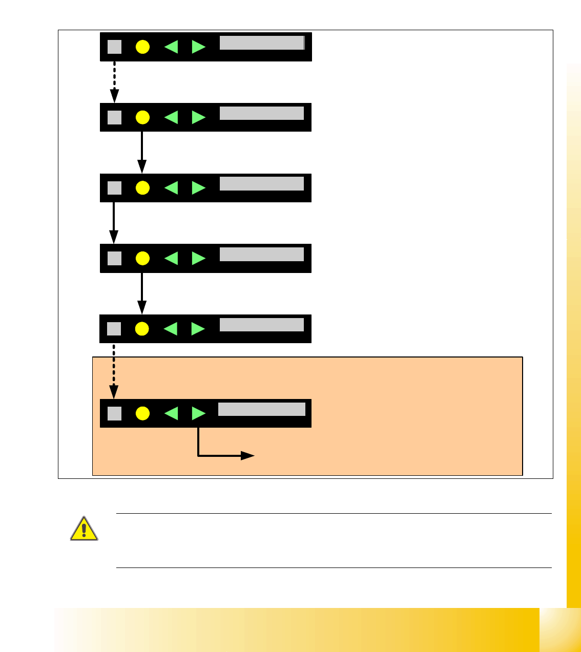
9.3.13 Activation and function in the Service technician menu
– The service menu is only temporary activ. After 1 minute if you don‘t press a button again the
menu goes back in the main menu. So it is not necessary to switch off the menu "Service tech-
nician" manual.
– In this additional menu is an reference run for the X-feeder possible, which are sometims nec-
essary, e.g.Software download, in this case the menu appears automatically.
Fig. 9.3 - 19 Servicemenu for reference run
ATTENTION: During the reference run with a tape you have to open the pick up window and no
foil in the foil removal unit and you
lost components.
Recommendation: Carry out the reference run with out a tape.
Spur 01 4mm
SIEMENS
Geschw. > > >
SIEMENS
Track01 4mm
Speed > > >
1. Button SET press, until it appears the display SPEED.
2. Button FOIL press long: Change in the Data menu
Referenz N
SIEMENS
Reference N
App.V. XX.YY
SIEMENS
App.V. XX.YY
3. Button SET press long: After release the button the menu service is activate.
Spur 01 4mm
SIEMENS
Track01 4mm
Boot.V. XX.YY
SIEMENS
Boot.V. XX.YY
4. Button FOIL press long: Change to the data menu back
Press the button SET , until the reference menu appears.
Press long: Start reference run.
After the reference run you have to confirm and
the display changed from N to Y

1 - 32
Student Guide SIPLACE X
9 Component handling Edition 09/2005
32
9.3.14 Error messages on X-feeder
Fig. 9.3 - 20 Error messages
Ready for Operation shows the green LED-Display,
Warning and Error messages shows the orange and red and additional the text on the operator panel
display.
Warning
Display LED-
Display
Description Solution
Remove Foil
orange You choose a function which is not possible if the
coverfoil in the removal unit tensioned (Cover foil
rocker is pressed down).
Would you like to carry out this function please remove the
coverfoil from the removal unit, so that the cover foil rocker
is up.
Error messages
Display LED-
Display
Description Solution
keine
red,
flashed
No Application software or with an error Î
Software load only the BIOS
Download the Application software new
Handle --->>
red
The feeder is log on, but the handle switch is off Push in the handle
Low Voltage
orange
24V Power supply Level don`t reached Check the power supply
Low Voltage
red
24V Power supply reached the power level, but
the power is break down
Check the power supply
Feed Timeout
TransTimeout
red
Transport cycle not ready in the defined time
(Timeout of the function „Feed“)
• Tape reel clamped?
• Component into the pick up area clamped?
• After the troubleshooting press the Button
FORWARD the transportstep will be finished and
find automatically the right position again.
Foil Torn
red
Foiltension not reached in a defined time. Maybe a foil is torn
Check the foil and foil tension
Foil PeelErr
red
Foil is not remove from the tape, but the tape is
moved.
Maybe the coverfoil clamped under the pick up window?
Foil Jam
red
Foil motor jam The gear is jam of the foil?
EEP-WriteErr
red
Data stored into the EEPROM not successfully
EEP-ReadErr
red
Reading the data from the EEPROM not
successfully
EEP-DataErr
red
Data stored into the EEPROM not successfully
In this case the position of the drive is not saved in the
EEPROM, so that a reference run is necessary Î Error
message confirm with the grey button and then appears
the menu for reference run confirm with the yellow button
(or see service menu point reference run).
Referenz o
Reference o
red
Information of the drive position not available Start a reference run
CAN BusError
red
CAN Bus Error If a reset not successful, send the feeder back to repair.
ParNotSaved!
red
Parameter not saved
ParWrongSave
red
Parameter wrong or not complete saved
Default parameter will be loaded automatically, that means
the last operator settings are overwrite Î e.g. the pitch is
after switch on the machine always wrong, exchange the
feeder control board.
BootFlashErr
FlashDataErr
red
Boot- or Application memory defect Feeder control board exchange

1 - 33
Student Guide SIPLACE X
Edition 09/2005 9 Component handling
33
9.4 Pneumatic tape cutter
9.4.1 Structure and function of the pneumatic tape cutter
The tapes guided into the slot (3) of the tape cutter via the empty tape duct (Pos.3 in Fig. 9.4 - 1).
The tape cutter is based on a horizontal frame (Pos.1) with a fixed cutting blade(6) and a moving
cutting blade that is driven by two pneumatic cylinders (Pos. 2). With every in and out movement,
the device cuts off the tape.
Proximity switches (Pos. 5) signal the position of the pneumatic cylinder pistons, and thus the
cutting blade. The electronic control unit (4) thus registers, for example, that a component that
remained in the tape was not cut. Cutting only takes place during placement. For operational
safety reasons, the tape cutter is integrated into the emergency stop circuit.
The pneumatic tape cutter is fixed on the frame of the docking unit with four screws and this, to-
gether with the empty tape duct is a complete unit.
Fig. 9.4 - 1 Pneumatic tape cutter
The Tape cutter is activated when the gantry is moving to the placement position. Alternating one
of the cylinders start to front position. The signal ’in front’ from the first cylinder start the cylinder
on the other side. Both signals ’blade in front position’ trigger control unit to withdraw both cylin-
ders at the same time.
(1) Horizontal frame 2. Pneumatic cylinder
3. Slot for empty tape 4. Electronic control unit
5. Proximity switch 6. fixed cutter blade