SiplaceX4_en.pdf - 第468页
1 - 36 S tudent Guide SIPLACE X 9 Component handling Edition 09/2005 36 9.4.3 Empty t ape duct At the inlet (Pos. 1) the empty tape duct receive the empty t ape from the feeders and dir ect them at the outlet (Pos. 2) to…
1 - 35
Student Guide SIPLACE X
Edition 09/2005 9 Component handling
35
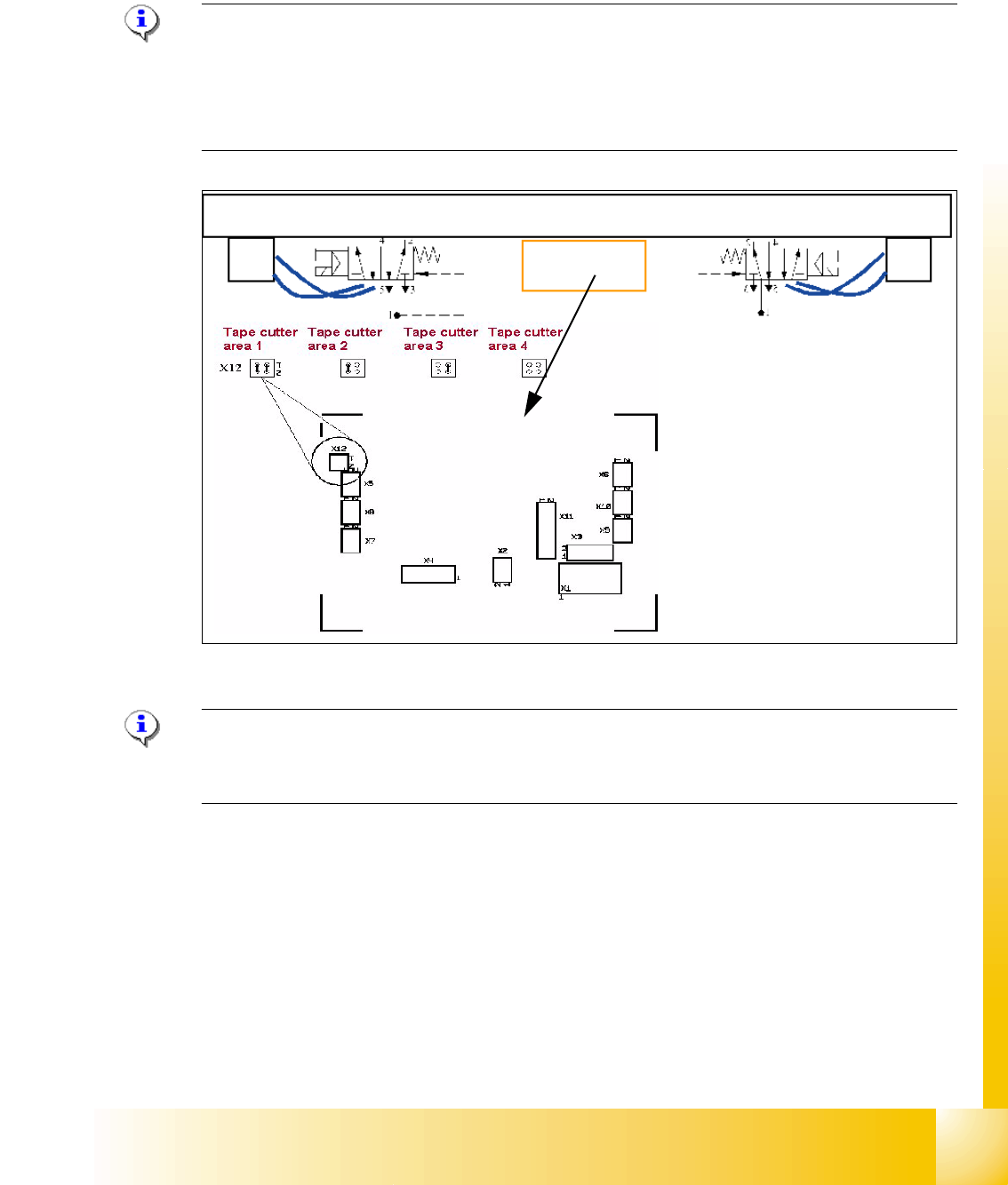
9.4.2 Jumper setting on the control unit at the tape cutter
The jumper for the CAN bus addressing must be set according to the corresponding location in
the machine.
Please Note:
The pneumatic hose of the actuator cylinders at both side are crossed. This is due to the electrical
actuator of the 5/2 way valves were mounted with the nose side facing the outer side of the cutter
unit. (At HS machines, the right actuator is mounted with the tube facing the inner side and there-
fore the hoses are NOT crossed).
Fig. 9.4 - 3 Jumper setting tape cutter
Please Note:
The spare part numbers of the tape cutter and cutter between the HF- and X-Machine are not the
same.
1
2
3
3
4
4
1. Power supply
2. Connector CAN Bus
3. BERO‘s for the valves
4. Connector 5/2 Way valve
5. Jumper setting
5
1 - 36
Student Guide SIPLACE X
9 Component handling Edition 09/2005
36
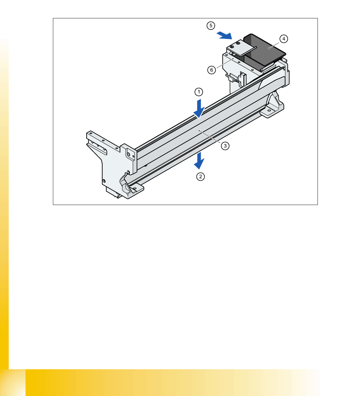
9.4.3 Empty tape duct
At the inlet (Pos. 1) the empty tape duct receive the empty tape from the feeders and direct them
at the outlet (Pos. 2) to the pneumatic tape cutter. There the tape is chopped up and passes down
the waste tape chute into the waste box below the component changeover table. For tapes with
deep tape pockets more than 17mm you have to remove the metal plate in the middle of the empty
tape duct. It is fixed with one screws on the left and one on the right side.
The empty tape duct is fixed to the pneumatic tape cutter with four screws.
9
Fig. 9.4 - 4 Used tape channel with component reject bin
(1) Inlet slot for empty tape
(2) Outlet slot for the empty tape above the pneumatic tape cutter
(3) Dividing plate for tapes < 17 mm (can be removed for tapes > 17 mm)
(4) Component reject bin
(5) Assembly position for the nozzle removal device
(6) Support for the nozzle changer (for 6 nozzle head the 2 outmost holes used; for 12 nozzle -,
and for the TWIN-head the middle and the left one is used)
The empty tape duct acts as a base for further modules:
– Removable component reject bin (Pos. 4)
– Assembly surface (Pos. 6) for the nozzle changers of the Collect&Place and TWIN-Head
– With the nozzle changer option is the removal device for nozzles of the 6nozzle C&P head is
mounted beside the reject box. Both C&P head types use the same nozzle removal unit.

Student Guide SIPLACE X
Edition 09/2005 Contents
1
Chapter
Table of contents
10 Modular conveyor . . . . . . . . . . . . . . . . . . . . . . . . . . . . . . . . . . . . . . . . . . . . . . . . . 3
10.1 Description of the functions . . . . . . . . . . . . . . . . . . . . . . . . . . . . . . . . . . . . . . . . . . . . . . . . . . . . . . 3
10.1.1 General . . . . . . . . . . . . . . . . . . . . . . . . . . . . . . . . . . . . . . . . . . . . . . . . . . . . . . . . . . . 3
10.1.2 Clamping . . . . . . . . . . . . . . . . . . . . . . . . . . . . . . . . . . . . . . . . . . . . . . . . . . . . . . . . . . 4
10.1.3 Width adjustment. . . . . . . . . . . . . . . . . . . . . . . . . . . . . . . . . . . . . . . . . . . . . . . . . . . . 4
10.1.4 Checking the PCB position on the conveyor sections . . . . . . . . . . . . . . . . . . . . . . . . 5
10.1.5 Stopping the PCB . . . . . . . . . . . . . . . . . . . . . . . . . . . . . . . . . . . . . . . . . . . . . . . . . . . 5
10.1.5.1 "Long Board" option HF . . . . . . . . . . . . . . . . . . . . . . . . . . . . . . . . . . . . . . . . . . . 5
10.1.5.2 "Alignment Pin" option . . . . . . . . . . . . . . . . . . . . . . . . . . . . . . . . . . . . . . . . . . . . 5
10.1.6 Lifting table . . . . . . . . . . . . . . . . . . . . . . . . . . . . . . . . . . . . . . . . . . . . . . . . . . . . . . . . 6
10.1.7 Firmware functions . . . . . . . . . . . . . . . . . . . . . . . . . . . . . . . . . . . . . . . . . . . . . . . . . . 6
10.1.8 Conveyor control TSP 201/301 supports the following options . . . . . . . . . . . . . . . . . 6
10.1.9 Structure of the single conveyor . . . . . . . . . . . . . . . . . . . . . . . . . . . . . . . . . . . . . . . . 7
10.1.10 Technical data - single conveyor . . . . . . . . . . . . . . . . . . . . . . . . . . . . . . . . . . . . . . . 8
10.1.11 Structure of the dual conveyor. . . . . . . . . . . . . . . . . . . . . . . . . . . . . . . . . . . . . . . . . 9
10.1.12 Technical data - dual conveyor . . . . . . . . . . . . . . . . . . . . . . . . . . . . . . . . . . . . . . . 10
10.1.13 Technical data - flexible dual conveyor . . . . . . . . . . . . . . . . . . . . . . . . . . . . . . . . . 10
10.2 Adjustments on the modular conveyor . . . . . . . . . . . . . . . . . . . . . . . . . . . . . . . . . . . . . . . . . . . . 11
10.2.1 Belt tension adjustment . . . . . . . . . . . . . . . . . . . . . . . . . . . . . . . . . . . . . . . . . . . . . . 11
10.2.1.1 Settings for the belt tension . . . . . . . . . . . . . . . . . . . . . . . . . . . . . . . . . . . . . . . 13
10.2.2 Setting the fixed conveyor rail (single and dual conveyor) . . . . . . . . . . . . . . . . . . . 14
10.2.2.1 Procedure to widen the conveyor to single conveyor mode: . . . . . . . . . . . . . . 15
10.2.2.2 Connect Lifting tables at the Dual Conveyor . . . . . . . . . . . . . . . . . . . . . . . . . . 15
10.2.2.3 Procedure to put back single conveyor mode: . . . . . . . . . . . . . . . . . . . . . . . . . 16
10.2.3 Move fixed conveyor rail for ’extended conveyor’. . . . . . . . . . . . . . . . . . . . . . . . . . 17
10.2.4 Checking the limit switch position . . . . . . . . . . . . . . . . . . . . . . . . . . . . . . . . . . . . . . 17
10.2.4.1 Adjusting the limit switch for initialize the driver . . . . . . . . . . . . . . . . . . . . . . . . 18
10.2.5 Width adjustment unit (Driver) . . . . . . . . . . . . . . . . . . . . . . . . . . . . . . . . . . . . . . . . . 19
10.2.5.1 Setting the BERO on the driver . . . . . . . . . . . . . . . . . . . . . . . . . . . . . . . . . . . . 19
10.2.5.2 Setting the ’pneumatic cylinder BERO’ on the driver . . . . . . . . . . . . . . . . . . . . 20
10.2.6 Setting and checking the laser light barrier for the stopper position . . . . . . . . . . . . 21
10.2.7 Setting the light barrier in the placement area. . . . . . . . . . . . . . . . . . . . . . . . . . . . . 22
10.2.8 Setting the light barrier in the input,- intermediate- and output conveyer . . . . . . . . 23
10.2.9 Adjusting the PCB clamping sensor . . . . . . . . . . . . . . . . . . . . . . . . . . . . . . . . . . . . 25
10.2.10 Option PCB clamping without clamping sensor. . . . . . . . . . . . . . . . . . . . . . . . . . . 26
10.2.11 Lifting table functions. . . . . . . . . . . . . . . . . . . . . . . . . . . . . . . . . . . . . . . . . . . . . . . 27
10.2.11.1 Setting the lifting table damping unit. . . . . . . . . . . . . . . . . . . . . . . . . . . . . . . . 28
10.2.11.2 Adjust the velocity of the lifting tables. . . . . . . . . . . . . . . . . . . . . . . . . . . . . . . 29