SiplaceX4_en.pdf - 第48页
1 - 24 S tudent Guide SIPLACE X 2 Overview Edition 09/2005 24 2.2.7 Construction of the X-Axis 2 Fig. 2.2 - 13 Structure of X-axis The X-axis consist of the following main modules: (1) Gantry X (Frame) (2) Mounting plate…
1 - 23
Student Guide SIPLACE X
Edition 09/2005 2 Overview
23
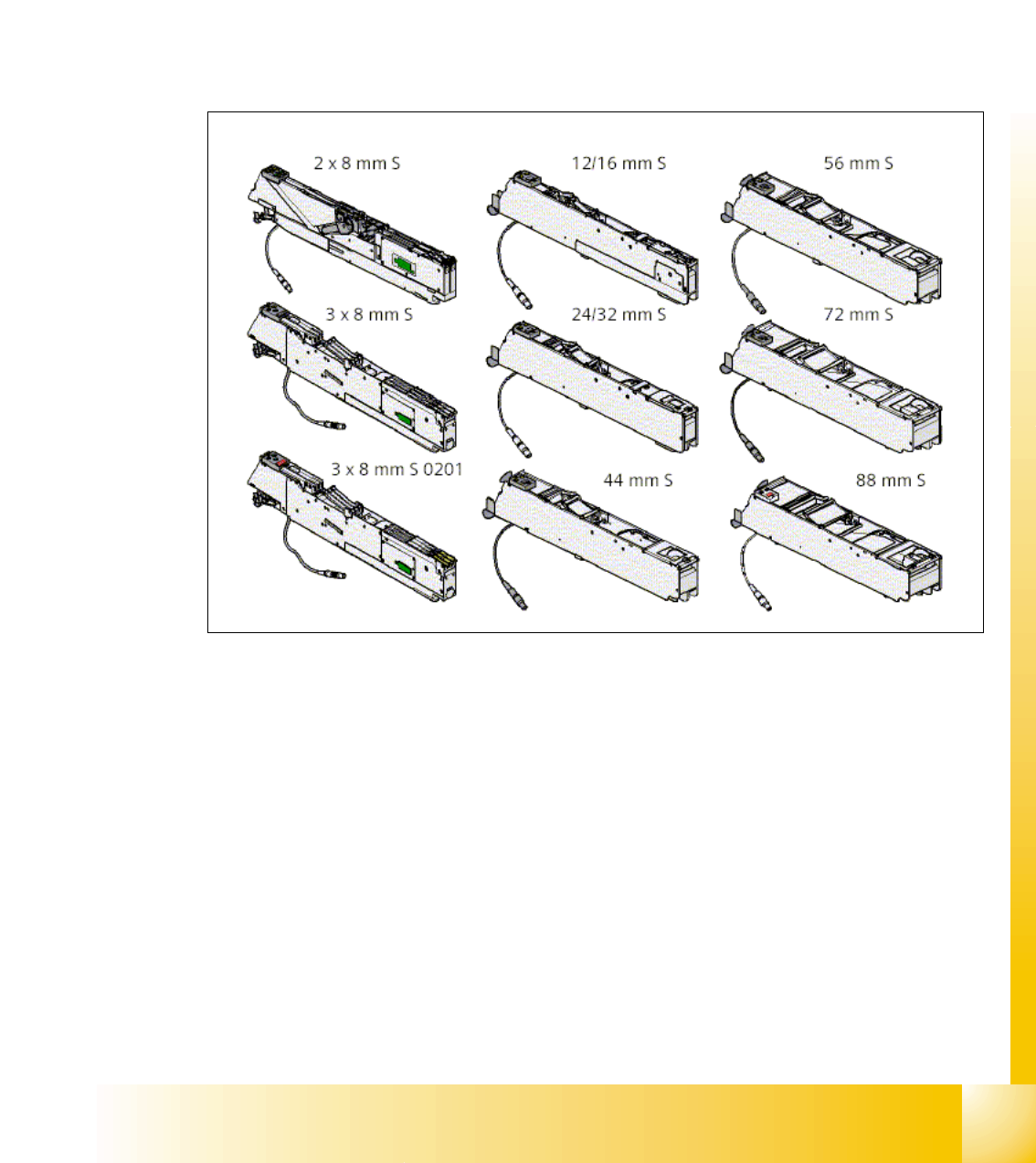
2.2.6.4 Overview S-Feeders
Description: Only 9 different feeder sizes are needed to feed tapes from 8 mm to 88 mm. Reels
are kept in the tape container on the component changeover table. The table cutter automatically
cuts the used tape. SIPLACE feeders have short cycle times and high-precision pick-up positions.
The feeders can also be used in other SIPLACE placement machines.
Bulk case feeders, vibratory stick feeders, surftape feeders, dip flux modules, component return
modules, and manual trays may be set up in addition to the tape feeders. Dummy feeders are
used at unassigned locations to protect the operators.
Fig. 2.2 - 12 Overview feeders
1 - 24
Student Guide SIPLACE X
2 Overview Edition 09/2005
24
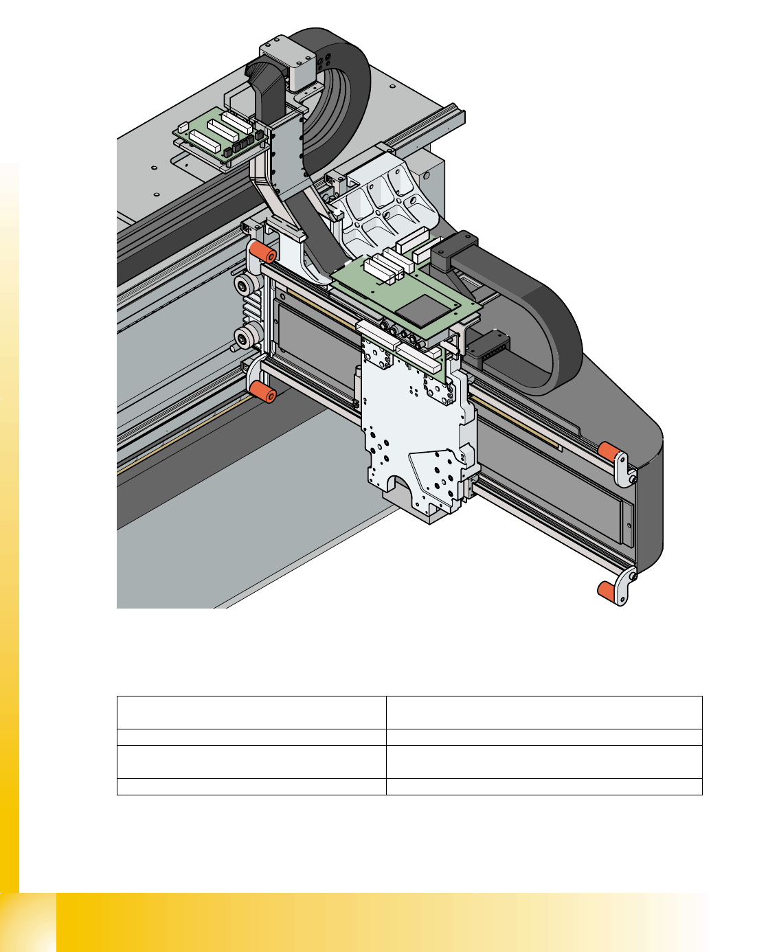
2.2.7 Construction of the X-Axis
2
Fig. 2.2 - 13 Structure of X-axis
The X-axis consist of the following main modules:
(1) Gantry X (Frame) (2) Mounting plate with head X-linear motor
(primary part)
(3) Linear incremental encoder (4) X-axis linear guides
(5) Linear drive for permanent magnet
(secondary part)
(6) PCB camera
(7) Head interface board (8) X-axis trailing cable

1 - 25
Student Guide SIPLACE X
Edition 09/2005 2 Overview
25
– The basic gantry is available in two versions. This is taken into account in the machine config-
uration! (SW 505)
– The Siplace X gantries has a metal strip for the travel range proximity switch in area (9).(Name
of the gantry version is CFK 04)
– The HF series gantries has a metal strip for the travel range proximity switch in area
(9a).(Name of the gantry version is CFK 02)
– New HF machine (which are signed with an " A "on the frame) have the gantry version CFK 04.
– The Siplace X gantries has a metal strip for the travel range proximity switch in area (9) and a
new trailing cable, which you can recognize with two additional pneumatic tubes on the right
side from the trailing cable. Name of the gantry version is CFK 06)
The following modules are installed on the head mount (2):
– PCB camera (6)
– Head boards (7) (head interface, head adapter)
– Incremental encoder
– Collect&Place head or twin head
The gantry arm (pos. 1 in fig. 2.2 - 13
) is made of carbon fiber material. This technology gives the
gantry arm high rigidity at minimum weight. The X-axis is driven by a linear motor. The secondary
part of the drive consists of a permanent magnet and is fixed to the gantry arm, while the primary
part is screwed to the head mount. The head mount is designed to fit all head types, which again
shows the great flexibility of SIPLACE machines.
2.2.7.1 X-Axis Technical Data
2
Drive direct, linear drive
Max. speed 2.5 m/sec
Travel range 471 mm
Mechanical travel range 480 mm
Measurement system Linear incremental encoder
Length of linear incremental encoder 520 mm
Resolution 1 µm