SiplaceX4_en.pdf - 第487页
1 - 19 S tudent Guide SIPLACE X Edition 09/2005 10 Modular conveyor 19 10.2.5 Wid th adjustment unit (Driver) 10.2.5.1 Setting the BERO on the driver The BERO (3) (see Fig. 10.2 - 9 ) pr ovides a signal fo r controlling …
1 - 18
Student Guide SIPLACE X
10 Modular conveyor Edition 09/2005
18
Legend
– Limit switches on the input conveyor: There are 5 limit switches below the conveyor rails near
the input conveyor. The limit switches are intended to prevent the conveyor rails moving to-
gether or against the basic conveyor frame.
– Limit switches on the output conveyor: There are 2 limit switches for the driver near the output
conveyor. They serve to protect the traveling range and initialize (right side) the driver for the
width adjustment.
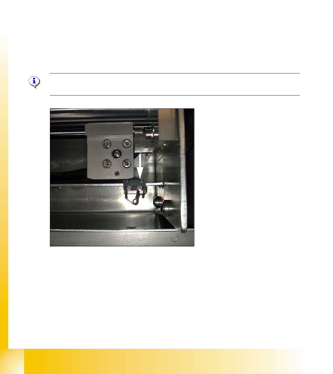
10.2.4.1 Adjusting the limit switch for initialize the driver
Please Note: This is only necessary in case of replacement of the switch or other mal functions
in width adjustment reference run.
Fig. 10.2 - 8 Limit /initialize switch
➠ Move the driver for the width adjustment by hand (via the toothed belt) to the conveyor rail.
➠ Loosen both screws of the limit switch (arrow in Fig. 10.2 - 8)
➠ Move the limit switch in the slot towards the driver and make sure, that the limit switch is safely
switched on.
➠ Check the status of the associated LED on the conveyor control (H41 ini TSP 301) .
➠ Fit the limit switch in this position.
➠ Calibrate the conveyor width via the SITEST program.
(1) Limit switch on the input conveyor - fitted
below the conveyor rail
(2) Limit switch on the input conveyor - fitted
below the conveyor rail
(3) Limit switch for the width adjustment unit
1 - 19
Student Guide SIPLACE X
Edition 09/2005 10 Modular conveyor
19
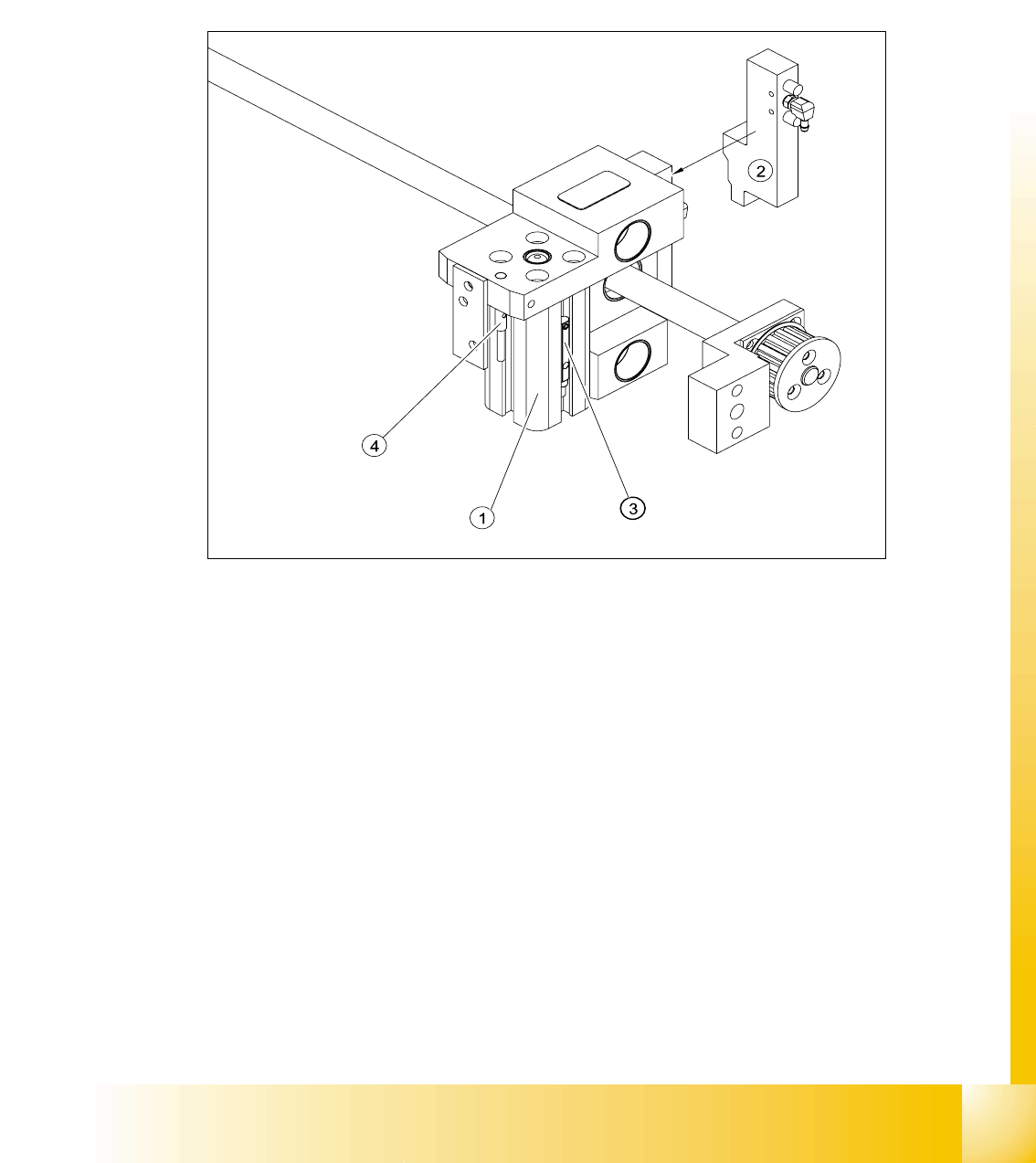
10.2.5 Width adjustment unit (Driver)
10.2.5.1 Setting the BERO on the driver
The BERO (3) (see Fig. 10.2 - 9) provides a signal for controlling the pneumatic valve of the driver.
Once the switching point ’conveyor rail reached’ is reached, the pneumatic valve engages the
conveyor rail.
Fig. 10.2 - 9 Overview of the BEROs on the driver for width adjustment
Legend to Fig. 10.2 - 9:
Setting Bero and actuator for transport rail position: 10
➠ When the BERO (4) is installed, it must not protude the driver.
➠ The switching point is set via the actuator on the conveyor rail
➠ Move the driver under the conveyor rail, then loosen the actuator using the screw.
➠ Place the driver at the final dimension of 2/10 mm, press the actuator onto the final dimension
and fix with the screw.
➠ Actuators on all conveyor rails have to be checked and maybe adjusted.
➠ Start SITEST and Calibrate transport.
(1) Short stroke cylinder (2) Solenoid valve
(3) BERO, pneumatic cylinder extended pos. (4) BERO, driver for transport rail position
1 - 20
Student Guide SIPLACE X
10 Modular conveyor Edition 09/2005
20
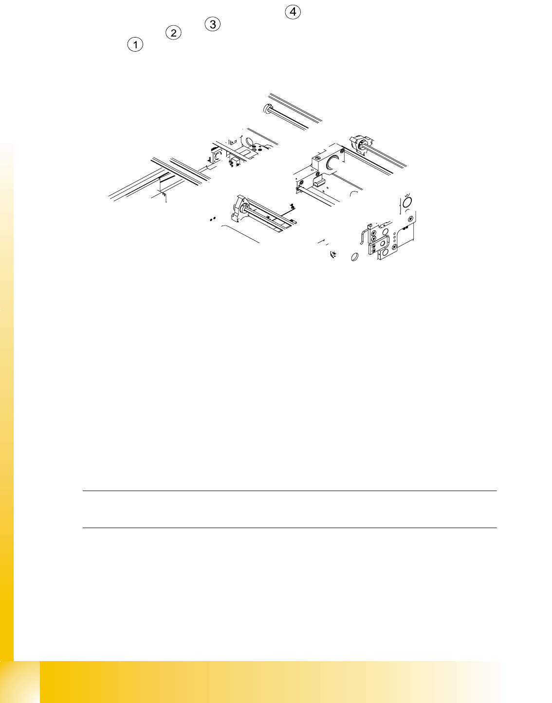
Fig. 10.2 - 10 Setting the actuator block for the width adjustment
Legend
➠ This setting must be repeated for all the conveyor rails.
10.2.5.2 Setting the ’pneumatic cylinder BERO’ on the driver
The BERO (3) (see Fig. 10.2 - 9) on the driver cylinder is designed to switch when the pin of the
driver is extended by the pneumatic cylinder so that the conveyor rail is engaged. This signal en-
ables the width adjustment motor.
Procedure: 10
Please Note:
The BERO on the pneumatic cylinder is set in the engaged state (but not in the free space!).
➠ Start SITEST
➠ Set any conveyor width. This moves the drivers directly under the conveyor rail.
➠ Start the I/O menu.
➠ Activate the pneumatic cylinder.
➠ Set the BERO on the pneumatic cylinder so that the LED (H35/H36/H37 TSP 301) lights up in
the engaged state (see Fig. 10.2 - 9).
(1) Actuator (2) Actuator fixing screw
(3) Driver (4) BERO, driver Transport rail position