SiplaceX4_en.pdf - 第490页
1 - 22 S tudent Guide SIPLACE X 10 Modular conveyor Edition 09/2005 22 Fig. 10.2 - 12 Focu ssing the laser beam Please Note: When you move the paper , the beam must follow along the edge of the PCB as accurately as po s-…
1 - 21
Student Guide SIPLACE X
Edition 09/2005 10 Modular conveyor
21
10.2.6 Setting and checking the laser light barrier for the stopper position
Danger:
Laser beams of laser class 2 occur at the laser light barrier transmitters, so no additional protective
measures are required.
You should never look into the laser beam, however.
Do the adjustment of the LASER Diode Beam direction only from the rear side of the LASER (left
machine side). Keep right side machine covers closed!
The laser beam deflection has greatest effect at the maximum conveyor width, it should always
be calibrated at the maximum conveyor width.
Please Note:
Check or reteach the PCB reference corner after adjustment of the laser light barrier!
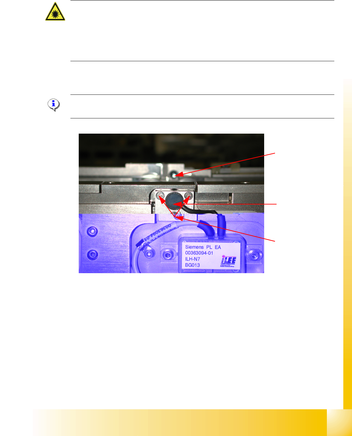
Fig. 10.2 - 11 Laser light barrier
Procedure:
➠ Set the maximum conveyor width.
➠ Choose General functions --> Cycle mode --> Safety mode switch on.
➠ Activate the relevant laser diode using the input/output functions in SITEST.
➠ Check the course of the laser beam. You can make the laser beam visible using a light-colored
PCB or a white sheet of paper (see Fig. 10.2 - 12).
➠ If necessary, use the adjusting screws to set the laser beam to the center of the receiver.
➠ Check the PCB reference corner and reteach, if necessary.
Laser diode
Laser receiver
Adjusting screws
3X
1 - 22
Student Guide SIPLACE X
10 Modular conveyor Edition 09/2005
22
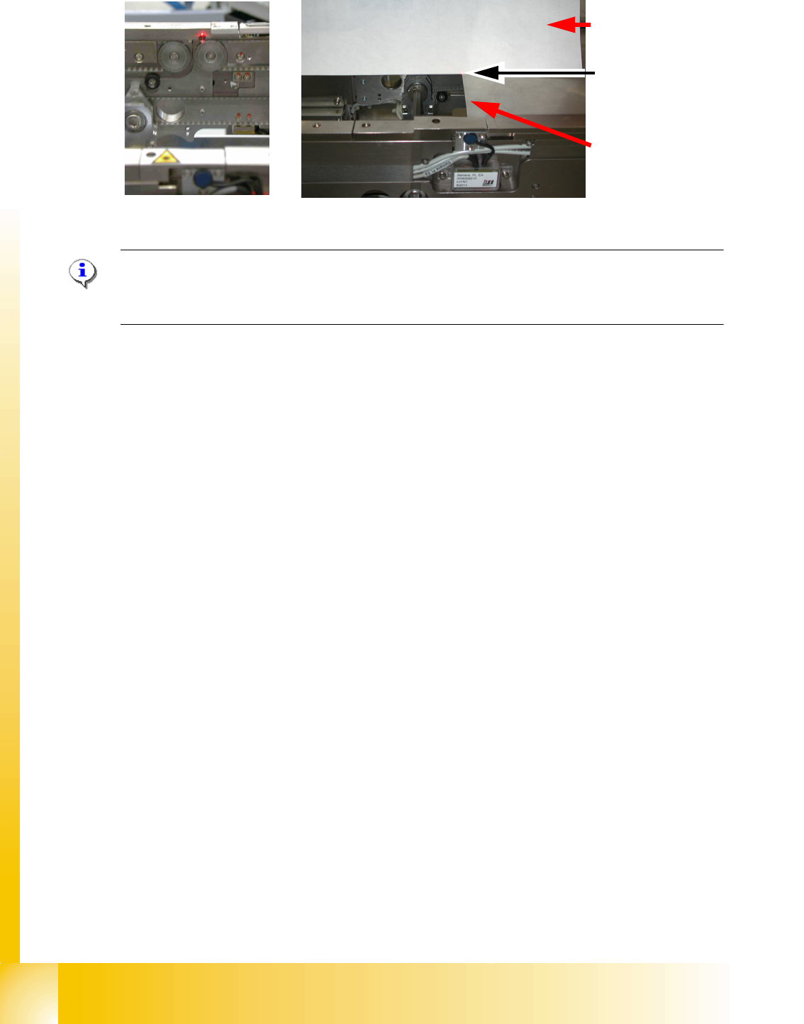
Fig. 10.2 - 12 Focussing the laser beam
Please Note:
When you move the paper, the beam must follow along the edge of the PCB as accurately as pos-
sible, with minimal deflection to the left and right.
10.2.7 Setting the light barrier in the placement area
Function: 10
– Switching on the laser light barrier
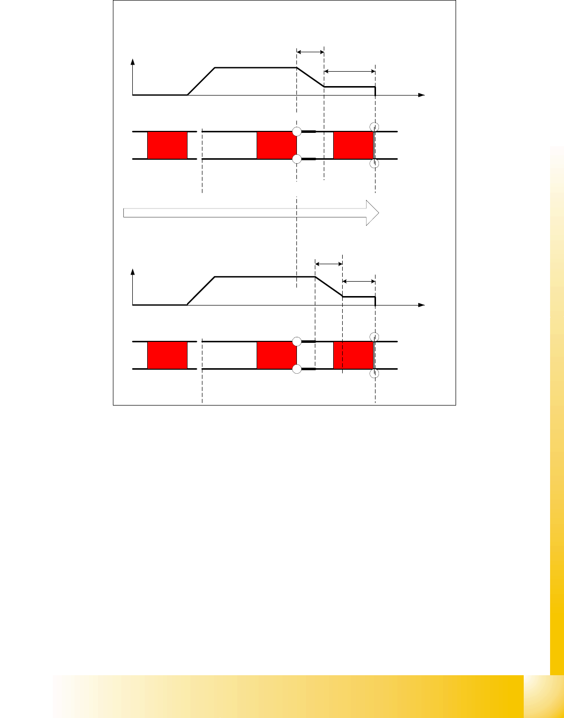
– Starting the PCB braking, see Fig. 10.2 - 13.
The light barrier in the placement area can be mounted in three different positions. The light barrier
is fitted in the direction to the input conveyer. The light barrier then trigger the LASER stopper and
slow down the PCB movement. The
slow PCB approach is teached automatically via soft-
ware.The travel profile for braking the PCB (see Fig. 10.2 - 13) is started in good time to allow the
PCB to be stopped reliably at the laser light barrier after no more than 100 ms.
Paper
PCB with the laser
beam parallel to it
Visible
laser beam
1 - 23
Student Guide SIPLACE X
Edition 09/2005 10 Modular conveyor
23
Fig. 10.2 - 13 Diagrams PCB braking
Due to the automatical teaching of the Slow PCB approach the time to reach the stopper position
is constant irrespective of the PCB weight. The transport time keeps constant.
10.2.8 Setting the light barrier in the input,- intermediate- and output conveyer
Function: 10
– Recognizing and stopping the PCB boards.
– PCB monitoring in the input conveyer, that means
Is a PCB recognized in the input conveyer and this PCB appears on the station GUI, then the
machine closes the interface to the previous station. With PCB boards with outbreaks it can
happen that the PCB, is stoped, however, the signal of the light barrier goes out and the inter-
face to the previous station is opened again. Then the next PCB would move into the input con-
veyer with the PCB still lying in the input conveyer. With PCB monitoring the PCB is moved
backwards and once again forwards, untill the light barrier switches.
Direction of PCB transport
Time (t)
< 100 ms
Light barrier
Laser
Travel profile
braking process
Start End
Placement areaInput belt
2nd board
Time (t)
Speed (v)
150 ms
Laser
Travel profile
braking process
Start End
Input belt
1st board
Speed (v)
Placement area
Light barrier