SiplaceX4_en.pdf - 第492页
1 - 24 S tudent Guide SIPLACE X 10 Modular conveyor Edition 09/2005 24 Assembly position for the receivers in the input-,intermediate- and output convey er 10 The receivers can be assemb led in four different posit ions,…
1 - 23
Student Guide SIPLACE X
Edition 09/2005 10 Modular conveyor
23
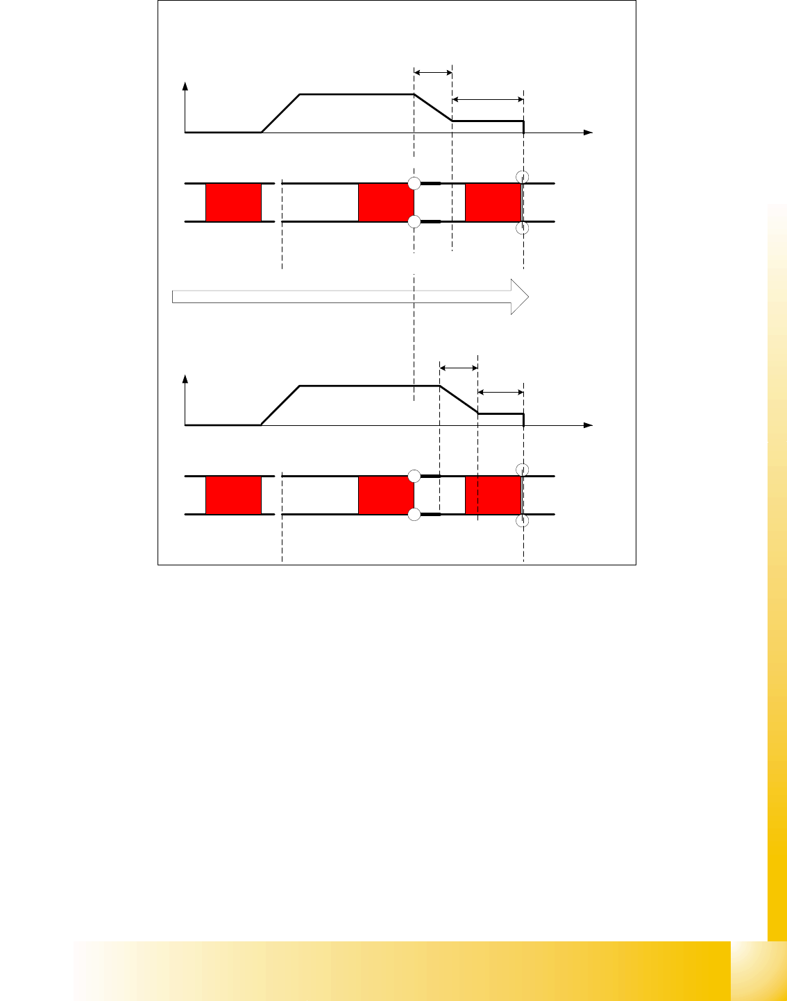
Fig. 10.2 - 13 Diagrams PCB braking
Due to the automatical teaching of the Slow PCB approach the time to reach the stopper position
is constant irrespective of the PCB weight. The transport time keeps constant.
10.2.8 Setting the light barrier in the input,- intermediate- and output conveyer
Function: 10
– Recognizing and stopping the PCB boards.
– PCB monitoring in the input conveyer, that means
Is a PCB recognized in the input conveyer and this PCB appears on the station GUI, then the
machine closes the interface to the previous station. With PCB boards with outbreaks it can
happen that the PCB, is stoped, however, the signal of the light barrier goes out and the inter-
face to the previous station is opened again. Then the next PCB would move into the input con-
veyer with the PCB still lying in the input conveyer. With PCB monitoring the PCB is moved
backwards and once again forwards, untill the light barrier switches.
Direction of PCB transport
Time (t)
< 100 ms
Light barrier
Laser
Travel profile
braking process
Start End
Placement areaInput belt
2nd board
Time (t)
Speed (v)
150 ms
Laser
Travel profile
braking process
Start End
Input belt
1st board
Speed (v)
Placement area
Light barrier
1 - 24
Student Guide SIPLACE X
10 Modular conveyor Edition 09/2005
24
Assembly position for the receivers in the input-,intermediate- and output conveyer 10
The receivers can be assembled in four different positions, this is necessary if you have LP‘s with
outbreaks and for small and wide PCB‘s. For normal PCB boards you can use the standard posi-
tion 3/4 of the receiver. If you have wide PCB‘s it make sense to use the position 1 or 2, because
the stop distance is longer.
– The receivers are fixed with two screws on the conveyer rail.
– Three drillings are in the conveyer rail, so there are two positions for mounting the receiver.
– Another two positions are posibile by turning around the sensor bracket at the receiver. (see
chapt.Fig. 10.2 - 14)
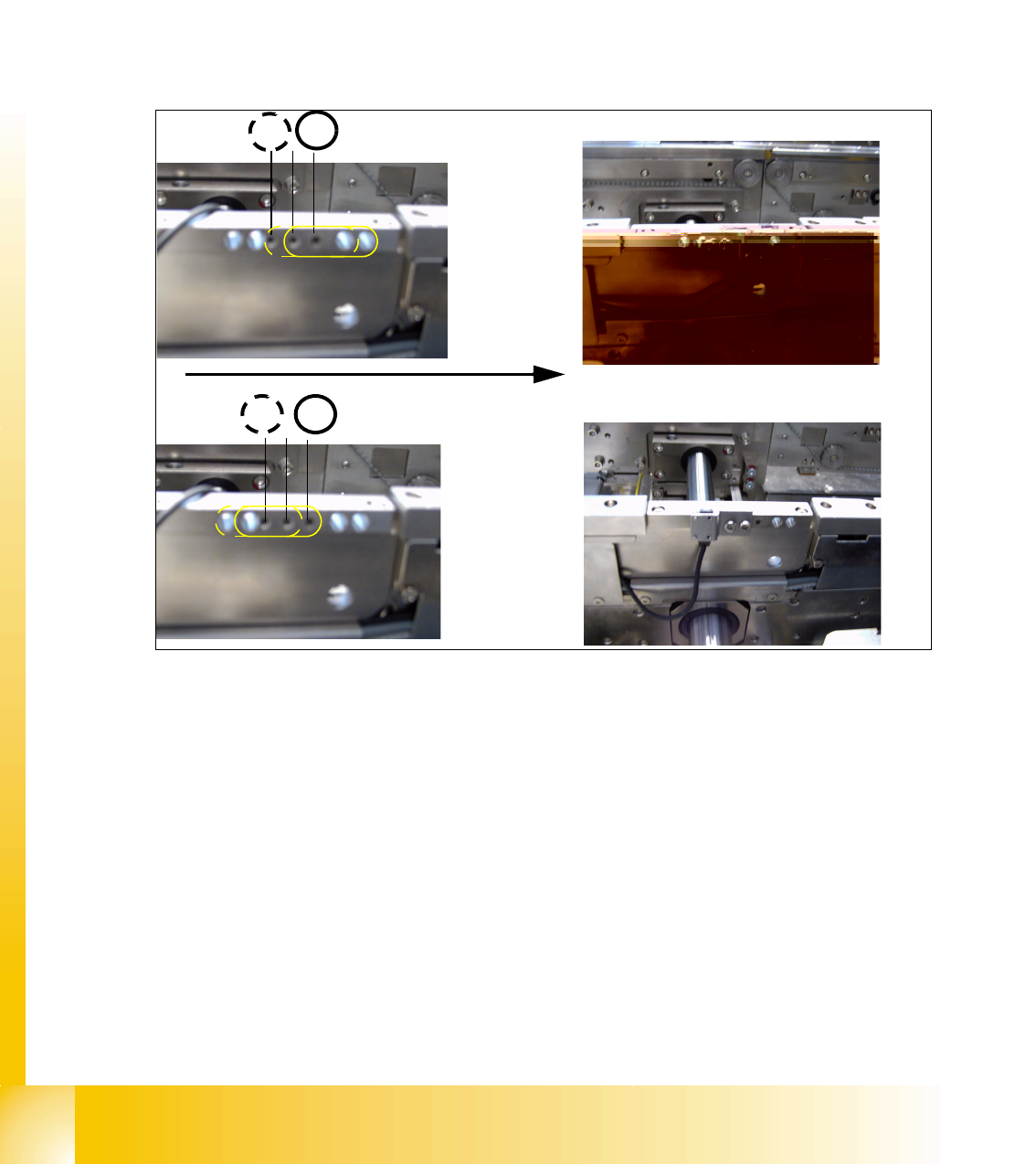
Fig. 10.2 - 14 Assemble position for the light barrier receivers
4
3
Example for Assemble position 3
1 2
Transport direction
Example for Assemble position 1
1 - 25
Student Guide SIPLACE X
Edition 09/2005 10 Modular conveyor
25
10.2.9 Adjusting the PCB clamping sensor
Please Note: Not for the X-Series machine!
The force sensor is not used since HF3 is introduced. The clamping of the PCB boards is recog-
nized with a check of the transport motor current (see chapter chapt.10.2.10).
Fig. 10.2 - 15 Clamping sensor for HF machine until Ma.No.xx, and not installed on HF3 machine
The clamp actuators (2), (3) are set so that the actuator (2) nearest to the clamping sensor (1)
responds first. To set the clamping sensor, first loosen the grub screw (see Fig. 10.2 - 15), then
push the grub screw in lightly.
Use Loctite 241. The maximum torque is 2,5 Ncm.
The clamping sensor input must respond to a slight pressure with the thumbs on the grub screw.
(
Sitest -> I/O menu 3 Conveyor 1 or I/O menu 4 Conveyor 2)
Attention
The piezo sensor can be damaged if the grub screw is tightened too far.
Use Loctite 241. The maximum torque is 2,5 Ncm!!
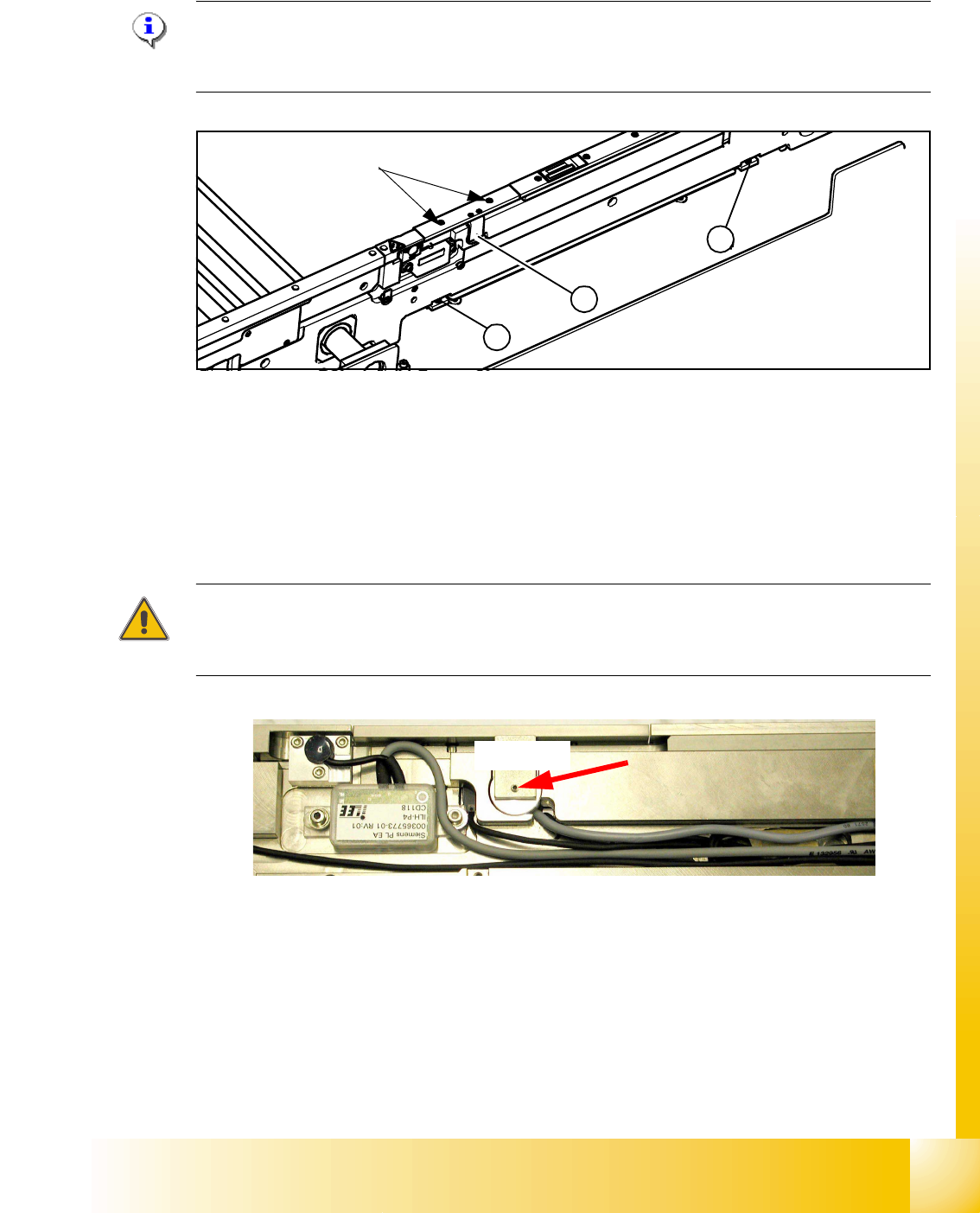
Fig. 10.2 - 16 Clamping sensor
Check: 10
The clamping sensor functions are checked with and without a PCB over the entire conveyor width
to ensure that it is not being affected by any unevenness at the lifting table plate. The clamping
sensor setting is checked with the lifting table running continuously.
An error message appears if the clamping sensor does not respond to the raised lifting table.
1
3
2
max 40Ncm!
Grub screw for setting the
clamping sensor
2,5Ncm!