SiplaceX4_en.pdf - 第495页
1 - 27 S tudent Guide SIPLACE X Edition 09/2005 10 Modular conveyor 27 10.2.1 1 Lif t ing t a ble functions Fig. 10.2.18 Lifting table un it Legend Lif ting table up func tion 10 Requirements for detec ting that the lift…
1 - 26
Student Guide SIPLACE X
10 Modular conveyor Edition 09/2005
26
10.2.10 Option PCB clamping without clamping sensor
Please Note:
The check whether a PCB is clamping correctly, is controlled with a motor current check of the
transport motor if the PCB board is clamped (Lifting table up). For check the function you could
put a distance plate under the conveyor rail, that the lifting table can not move to upper position.
This check of PCB clamping is switched OFF, when you have activate the clamping sensor or the
option ceramic substrate centering is installed.
Function describtion: 10
– The PCB moves into the placement area, it is recognized by the light barrier, stops at the laser
and the lifting table moves up.
– Check PCB clamping: The transport motor in the placement area start again. Is the PCB clam-
ped correctly the motor current rise up and reach an defined threshold value. The motor is
stopped and placement process starts.
– If the motor current don‘t reach the threshold value, the PCB board is not clamping correctly.
– On the station computer a error message appears. With the "Start" - button you could repeat
the procedure with "Cancel" the PCB board moves to the output conveyor.
– The lifting table moves down, the PCB board moves back in the placement area and move to
the laser again clamp the board and check it again.
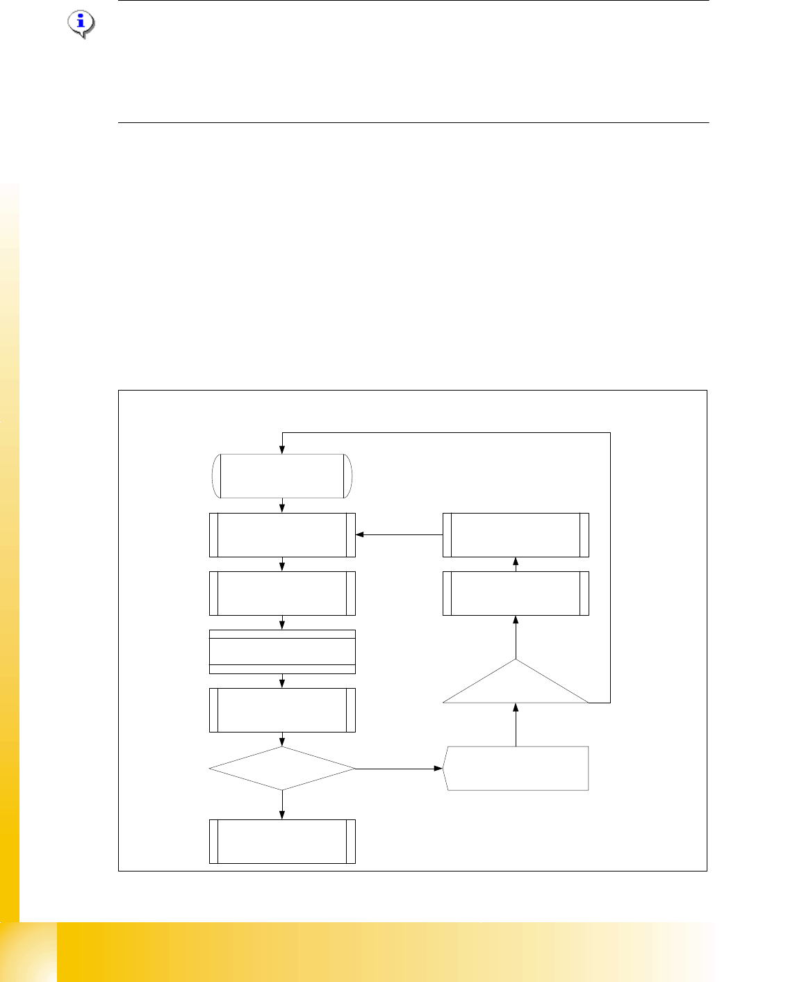
Fig. 10.2 - 17 Flow diagram Check PCB clamping
Threshold value motor
current reached?
Start
PCB board move in the
placement area
Description of the function Check the PCB
board clamping
PCB is recognized by the light
barrier ==> activated the LASER
and start the travel profile
Brake application
LP stops at the LASER and the
lifting table moves up
Start Placement process
Check the clamping
Start Transport motor in the
placement area again
PCB clamping correctly?
Lifting tablr moves down
==> clamping open
PCB moves back and the
prozedure will be repeat
Station computer Error message
"Clamping error transport"
Start-Button
Cancel
YES
NO
1 - 27
Student Guide SIPLACE X
Edition 09/2005 10 Modular conveyor
27
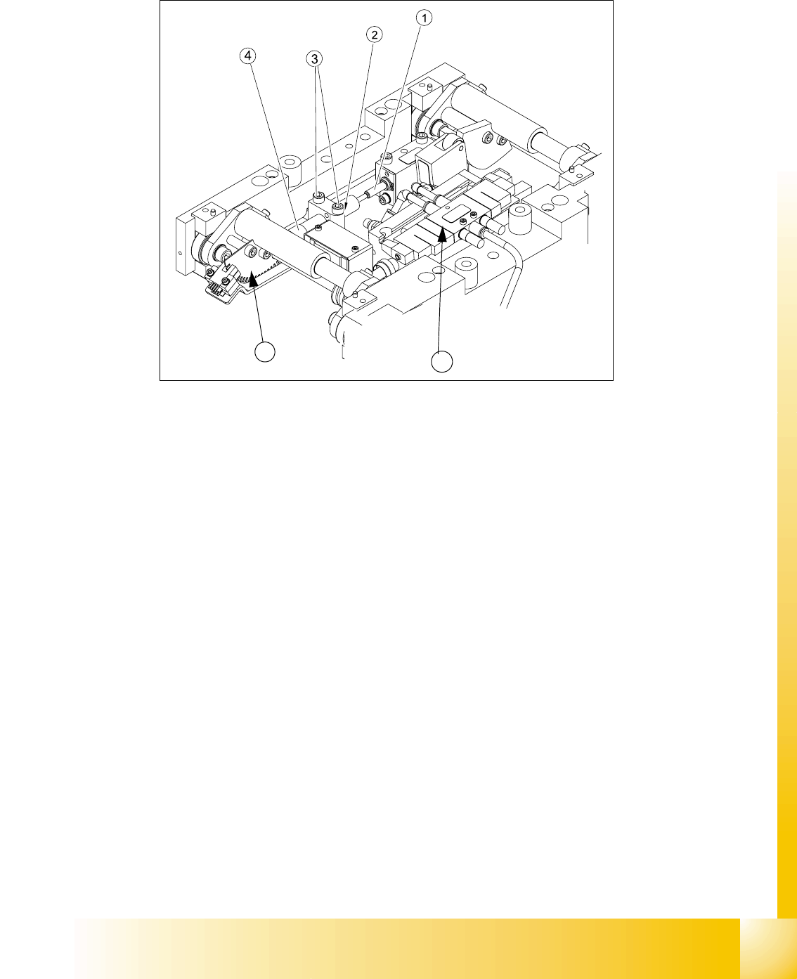
10.2.11 Lifting table functions
Fig. 10.2.18 Lifting table unit
Legend
Lifting table up function 10
Requirements for detecting that the lifting table is up:
1. 7-8 increments on the incremental encoder
2. Clamping sensor (force sensor) (not used in future see chapter chapt.10.2.10)
3. Dynamic response of approx. 500 ms
Lifting table down function 10
Requirements for detecting that the lifting table is down:
1. 7-8 increments on the incremental encoder
2. BERO on the lifting table cylinder
3. Dynamic response of approx. 480 ms
(1) Actuator lifting table drive (2) Lock nut damper
(3) Fixing screws damper bloc (4) adjustable damper
(5) 3/5 way solenoid valve mounted on lifting
table drive cylinder
(6) Fork-type light barriers / incremental disk
5
6
1 - 28
Student Guide SIPLACE X
10 Modular conveyor Edition 09/2005
28
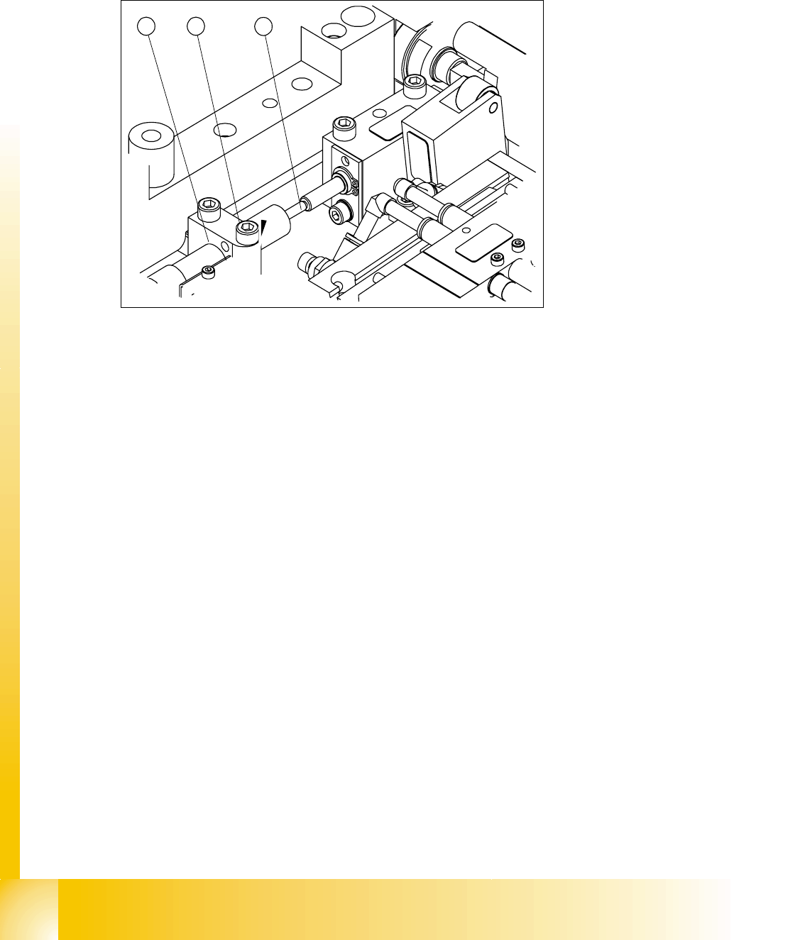
10.2.11.1 Setting the lifting table damping unit
The damping unit allows the lifting table to move gently upwards. When the PCB is clamped, it
also prevents excessive bounce by the PCB.
Fig. 10.2 - 19 Setting the damping unit
Legend
Setting: 10
➠ Check whether the damping unit is fixed in the fixing block with the lock nut and that the damp-
ing unit is lying gently against the actuator. In this default setting, the lifting table should move
up gently.
➠ If this is not the case, loosen the lock nuts and screw the damping unit further into the fixing
block by approximately one turn.
➠ Start SITEST and move the lifting table up.
➠ The lifting table must move up gently.
The PCB clamping should not engage audibly and there should be no PCB clamping error
message.
➠ Check the speed of the lifting table cylinder and correct if necessary (see section 10.2.11.2)
(1) Damping unit (cylinder) (2) Plunger and actuator
(3) Bearing block and lock nut
1 2
3