SiplaceX4_en.pdf - 第510页
1 - 4 S tudent Guide SIPLACE X 1 1 Sitest Edition 09/2005 4 The main view of the user interf ace of the test progra m will appear on the screen shortly af ter- wards. ➠ Select the desired language . 1 1.1.1.2 T erminatin…
1 - 3
Student Guide SIPLACE X
Edition 09/2005 11 Sitest
3
11 Sitest
WARNING
The SITEST test program may only be used by staff members of SIEMENS AG L&A EA, or spe-
cially trained customer staff. Improper use of this test program will result in severe damage to the
machine and will pose a hazard to the operating personnel.
11.1 Overview SITEST
SITEST is a program which allows the various functions of the individual modules of the
SIPLACE X to be tested.
Overview of SITEST functions
– General SITEST functions
–Functions for machine settings
– Functions for setting the dynamics of the axes
– Calibration functions
– Mapping functions
You can execute these functions using SITEST. You will find information on how to do this and
details on the interfaces in this chapter, software instruction for Sitest and by using the online Help
function while working with SITEST. In addition, you will find a number of practical examples de-
scribed in the online Help system.
11.1.1 Starting/Terminating the Test Program
11.1.1.1 Starting
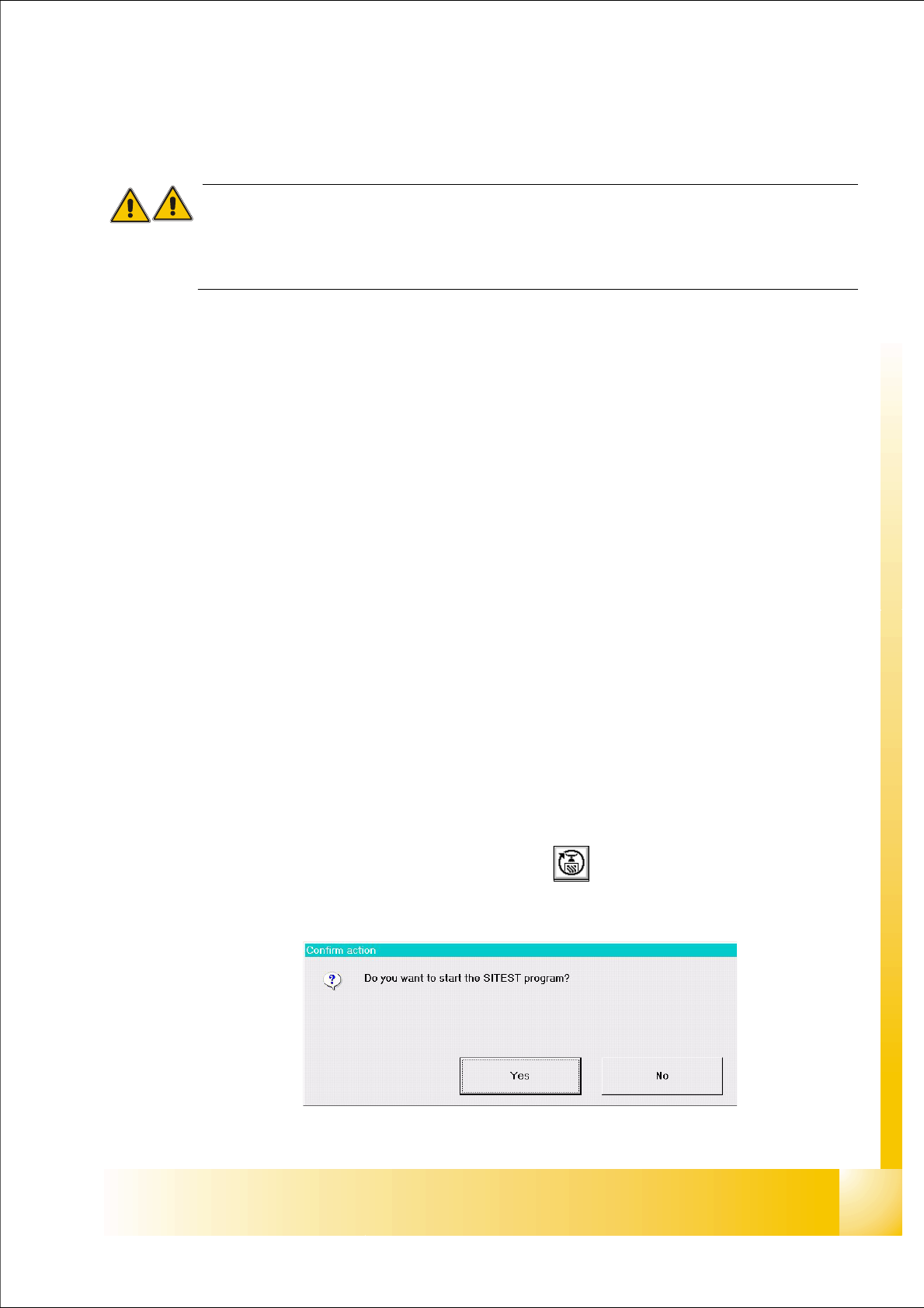
➠ On the user interface for the station, click on the icon (see User’s Manual SIPLACE )
The test program is started.
Fig 7.1 - 1 Confirmation "Start Sitest"
1 - 4
Student Guide SIPLACE X
11 Sitest Edition 09/2005
4
The main view of the user interface of the test program will appear on the screen shortly after-
wards.
➠ Select the desired language .
11.1.1.2 Terminating
There are three ways of properly terminating the test program, i.e. either
– from the main view via the
Mode menu, by selecting the menu command Exit ,
– using the key
ESC
– or by proceeding as described in the following.
Note:
Only the key ESC permits the test program to be terminated from any view.
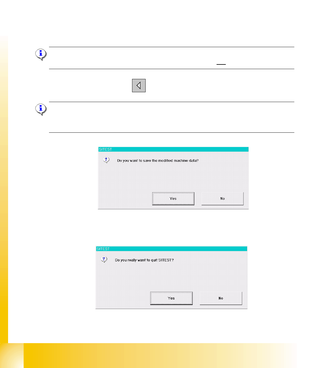
➠ In the main view, click on the icon.
Note:
If newly determined or edited machine data have not been saved yet, an appropriate message will
be displayed before exiting the program prompting you to save the data (see example below).
Click on the
Yes button in the dialog box if you wish to save the data on terminating the test pro-
gram, or click on
No if you do not wish to save the data.
The following dialog box opens.
➠ Click on the Yes button. The test program is terminated.
1 - 5
Student Guide SIPLACE X
Edition 09/2005 11 Sitest
5
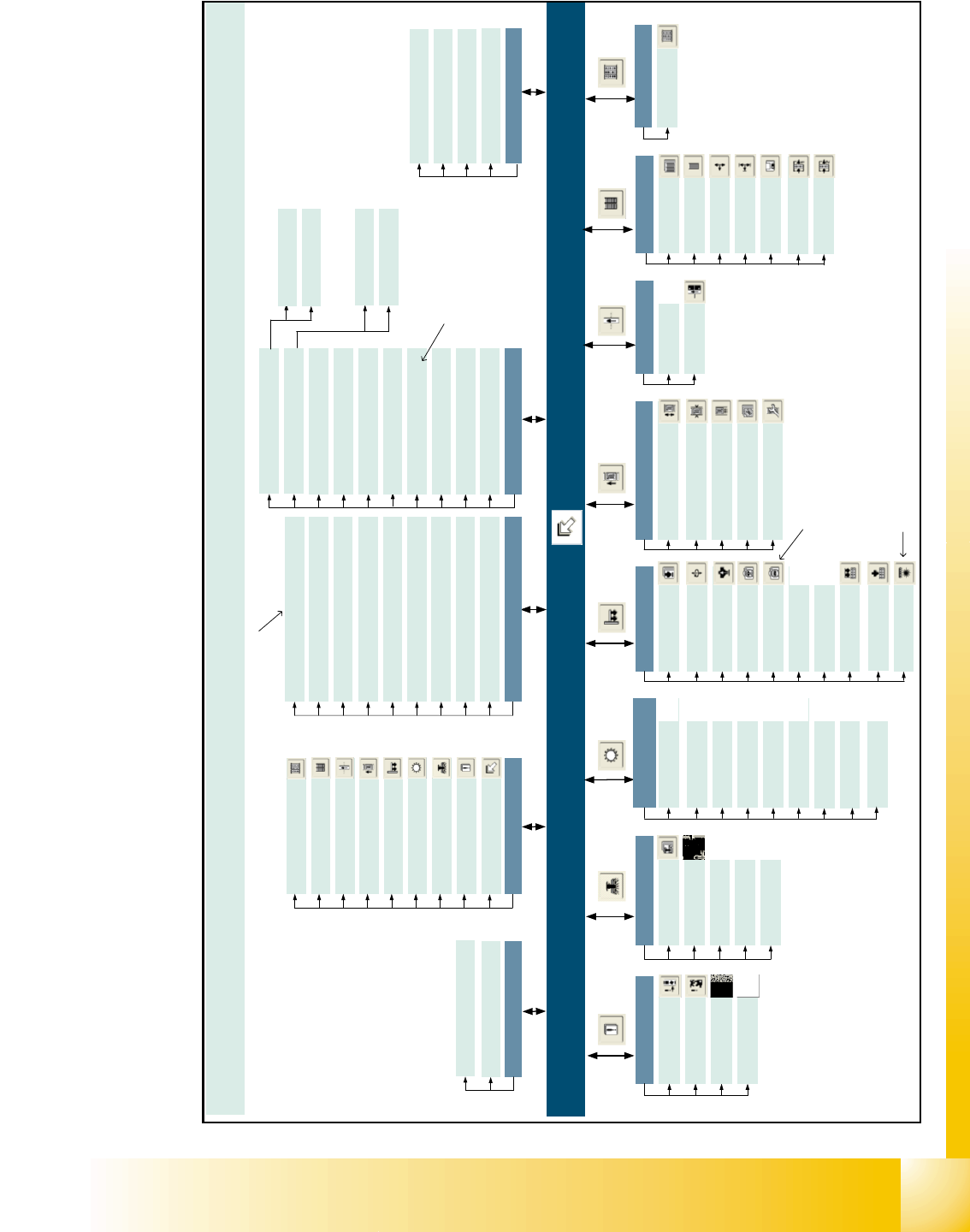
11.1.2 Overview Siplace X2
SITEST version 601.xx Menu and toolbar in the main view
Machine type: SIPLACE X2
Mode
Shut down computer...
Exit Esc
View
In-/outputs F9
MTC F8
Tables F7
PCB conveyor F6
Twin Head F5
C&P heads / F4
RV heads
Gantries F3
Error F2
Main view F1
Save machine data
Settings
Access level...
Copy machine data...
Edit machine data… *
Firmware download...
Machine configuration...
Whispering down the line...
Recovery placement...
Help
Contents Ctrl+Alt+F1
Help Alt+F1
Use help
Info...
Main view [F1]
[F2]
Error
Track errors
Machine errors
Transport errors
General errors
[F3]
Gantry functions
Gantries
Axis functions
Calibrate position
PCB camera
functions
PCB mapping
[F4]
C&P heads /
RV heads
Functions
Axes
Holding/reject circ./
turning station
Placement and
pick-up circuit
Head and
component camera
Head mapping
Nozzle changer,
head functions
Nozzle changer,
magazine functions
Component sensor
Twin Head
Functions
Axes
Head board
Component
camera 1
Component
camera 2
*
[F5]
Calibrate
Twin Head
Head mapping
Nozzle changer,
head functions
Nozzle changer,
magazine functions
Coplanarity
module
*
PCB conveyor
PCB conveyor functions
Adjust and measure
PCB conveyor width
Adjust and test
conveyor speed
Calibrate conveyor
and functions
Options and configuration
[F6]
[F7]
Tables
Functions
Calibrate
pick-up position
Functions
Tower functions
Axes
MTC
[F8]
[F9]
Inputs/outputs
1 - 15
Inputs/outputs
Settings
Machine data
Inputs/outputs 1
Inputs/outputs 2
*
C
a
n
o
n
l
y
b
e
s
e
l
e
c
t
e
d
o
n
t
h
e
"
S
e
r
v
i
c
e
(
S
i
e
m
e
n
s
)
"
a
c
c
e
s
s
l
e
v
e
l
* Can only be selected when the
coplanarity module is configured
* Can only be selected when the
component camera 2 is configured
* You can only select the cameras that
are currently configured for the head
on the relevant gantry.
General functions
Run options… Alt+t
PCB camera gantry 1 > Alt+1
Component camera gantry 3 > Alt+2 *
Component camera 1 gantry 1 > Alt+3 *
Component camera 2 gantry 1 > Alt+4 *
PCB camera gantry 3 > Alt+5
Component camera gantry 3 > Alt+6 *
Component camera 1 gantry 3 > Alt+7 *
Component camera 2 gantry 3 > Alt+8 *
Head exchange
Language
English
German
Head 3…
Head 1...