SiplaceX4_en.pdf - 第514页
1 - 8 S tudent Guide SIPLACE X 1 1 Sitest Edition 09/2005 8 1 1.1.5 Icons in the main view and their sub menus 1. 2. 3. Errors Call-up of the display o f the ge ne ra l erro rs. C al l - up of t h e t r an s por t e rror…
1 - 7
Student Guide SIPLACE X
Edition 09/2005 11 Sitest
7
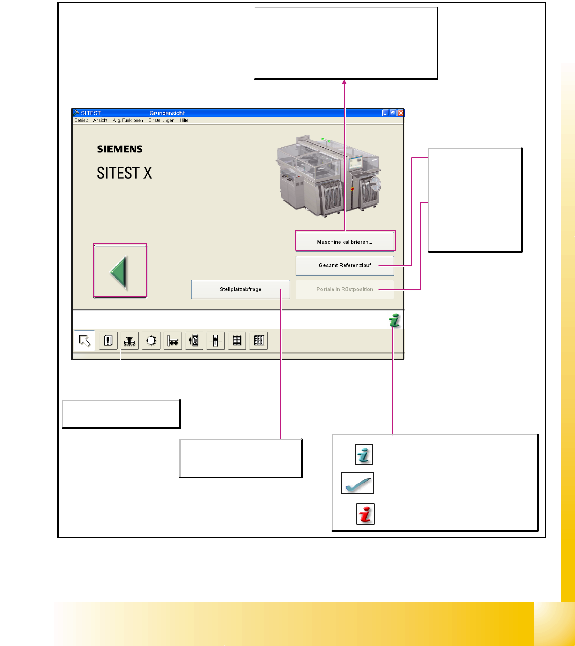
11.1.4 Main view Sitest
After starting the SITEST test program, the main view of the user interface will be displayed. The
operator can control the basic functions of the program from this view. He can return to the main
view from all the other displays.
Location interrogation
Available locations are queried as to
whether component tables or MTCs
(matrix- tray changers) are attached.
Cancels processing and exits the
SITEST test program.
Calibrate machine...
Opens the Calibrate entire machine dialog box. All
functions which are needed to calibrate the entire
machine are offered here.
Note
Before the calibration operation is carried out, a reference
run must be carried out for the heads and gantries.
Overall reference run
Starts the reference run
for all head and gantry
axes of the machine and
initializes the conveyor.
Gantries in setup
position
Moves the gantries from
the feeder area to allow
access to the component
tables with the feeders.
Starts a help system which lists possible causes
of the current error along with corrective
measures.
The current error message is deleted from the
status bar.
Provides context-sensitive help on the current
view.. This also provides a short description of all
the displayed operating elements.
1 - 8
Student Guide SIPLACE X
11 Sitest Edition 09/2005
8
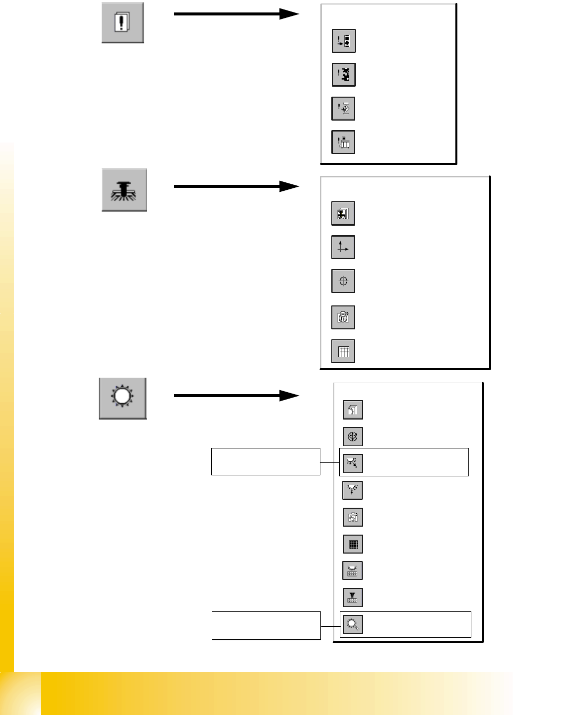
11.1.5 Icons in the main view and their sub menus
1.
2.
3.
Errors
Call-up of the display
of the general errors.
Call-up of the transport
error display.
Call-up of the machine
error display.
Call-up of the track
error display.
Gantry
Call-up of the display of the
gantry's PCB camera
functions.
Call-up of the gantry functions.
Call-up of the display of the
gantry axis functions.
Call-up of the display of the
gantry's calibration functions.
Call-up of the display of the
gantry's PCB mapping
functions.
Revolver heads
Call-up of the display of the
functions of the revolver head.
Call-up of the display of the axis
functions of the revolver head.
Call-up of the display of the
functions of the revolver head in
the holding and reject circuit.
Call-up of the display of the
functions of the revolver head in
the placement and pick-up circuit.
Call-up of the display of the
mapping functions of the revolver
head.
Call-up of the display of the RV
camera functions.
Call-up the view for the functions
of the revolver head component
sensor.
Opening the screen for the
magazin functions of the revolver
head nozzle changer.
Opening the screen for the head
functions of the revolver head
nozzle changer.
function only for
C&P 6/12
function only for
C&P 6/12
1 - 9
Student Guide SIPLACE X
Edition 09/2005 11 Sitest
9
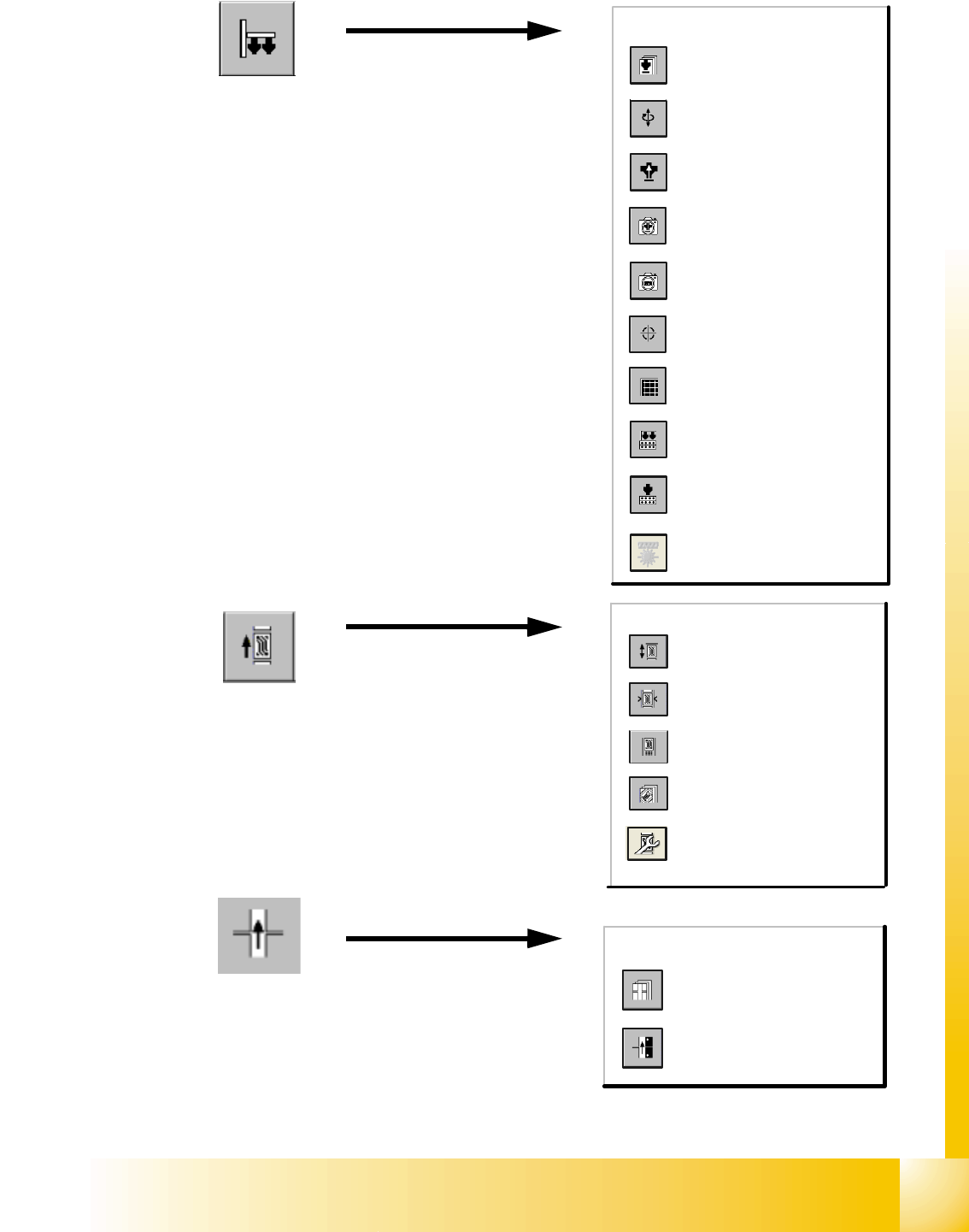
4.
5.
6.
Twin Head
Calling up the view for the
functions of the Twin Head.
Calling up the view for the axis
functions of the Twin Head.
Calling up the view for the head
board functions.
Calling up the view for the IC
camera functions.
Calling up the view for the FC
camera functions.
Calls up the view of the
calibration functions for the Twin
Head.
Calling up the view for the
mapping functions of the Twin
Head.
Calls up the view for the head
functions of the nozzle changer
for the Twin Head.
Calls up the view for the
magazine functions of the nozzle
changer for the Twin Head.
button for coplan- module
PCB-Conveyor
Call-up the Conveyor Functions
view.
Call-up the screen for setting
the conveyor speed.
Call-up of the display of the
conveyor width settings.
Call-up the screen displaying
the PCB transport functions.
Call-up the screen displaying
option and configuration
(conveyoir width or transport
modus)
Tables
Call-up of the display of the
component table functions.
Call-up of the display for the
calibration of the component
table pick-up position.