SiplaceX4_en.pdf - 第519页
在线预览 SiplaceX4_en.pdf PDF 文档。
1 - 12
Student Guide SIPLACE X
11 Sitest Edition 09/2005
12
11.2.1 Calibration in general
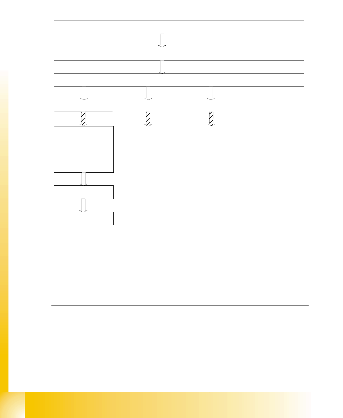
Fig. 11.2 - 1 General sequence to calibrate the machine
Note:
Since the head modularity concept means that either a Twin Head or a C&P head can be fitted to
each gantry, the functions displayed for processing area 1(PA1) and processing area 2 (PA2) re-
spectively may vary. The functions described for PA1 and PA2 below apply for a Twin Head con-
figured on gantry 3 and a C&P head configured on gantry 1 on a X2 machine.
Sequence of calibrate the Siplace X machine with SW 601
Preperation the machine
All heads and cameras..
Sitest: Button "Calibrate machine...."
Calibrate and
teach of positions
(conveyor edges,
conveyor width,
PCB reference
corner, pick-up
positions)
PCB Mapping
Head Mapping
Gantry 1
(X2/X3/X4)
1 - 15
Student Guide SIPLACE X
Edition 09/2005 11 Sitest
15
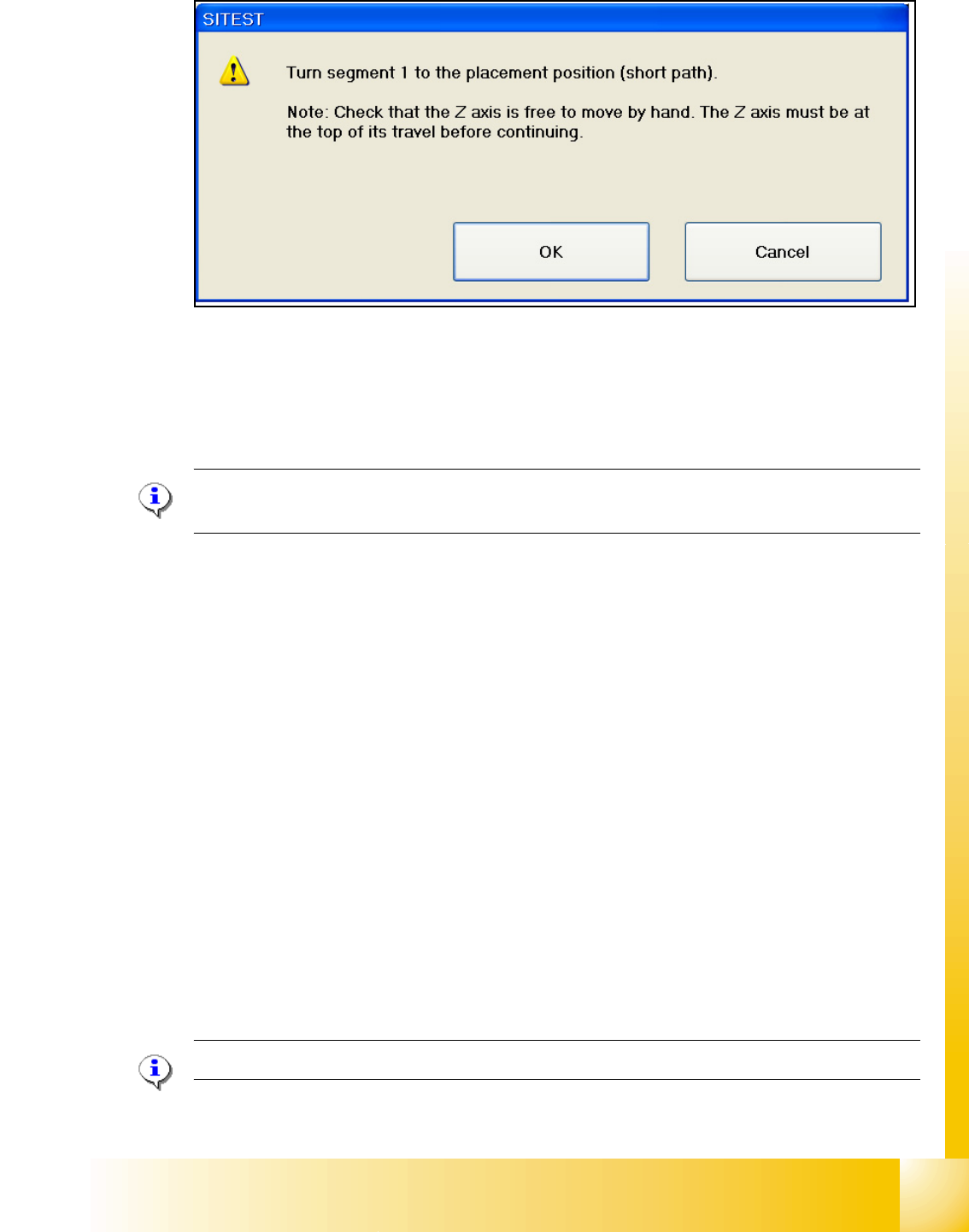
– Follow the Information and press the Start button on the maschine.
–Press OK
Now the head is calibration the Z- and Star zero point correction and save the new values in the
Achs_ver.ma and on the EEprom.
NOTE :Is this function not successful, please check the Travel range of the Z-axis.
The max. and min. travel range of the Z-axis(C&P20) are 34000 digits and -200 digits.
Function description: 11
– The Z-Axis move up with the current sensor mode and set the counter to 0.
– Then the Z- axis moves down to 18000 digits until the ball bearing of the Z- axis is between the
raceway of the star axis.
– The star turns left and right and calculated the average value. This is the new zero point cor-
rection (
zpc) value of the star axis.
– The Z- axis moves further down until the ball bearing (Segment) is in the center of the raceway
gap.
– The star turns right into the gap of the raceway and the Z- axis push up the ball bearing against
the raceway. The Z-axis position is read.
– Now the Z- axis position is read on the left side from the raceway gap with the same procedure,
like the right side.
– Afterwards the new zero point correction of the Z- axis is calculated in the following way :
Z- position - diameter ball bearing - thickness of the raceway = new zpc Z- axis
NOTE : The data is directly stored in the Achse_ver.ma and in the EEPROM of the head.