SiplaceX4_en.pdf - 第523页
1 - 18 S tudent Guide SIPLACE X 1 1 Sitest Edition 09/2005 18 1 1.2.6 ALL heads and cameras Depends of the con figuration the X - machin e about the head s on Gantry 1 and Gantry 2 the cal- ibration seqeuence is dif fere…
1 - 17
Student Guide SIPLACE X
Edition 09/2005 11 Sitest
17
11.2.5 Operation for calibrating the entire machine
NOTE : see precondition for calibrating, chapter 11.2.2
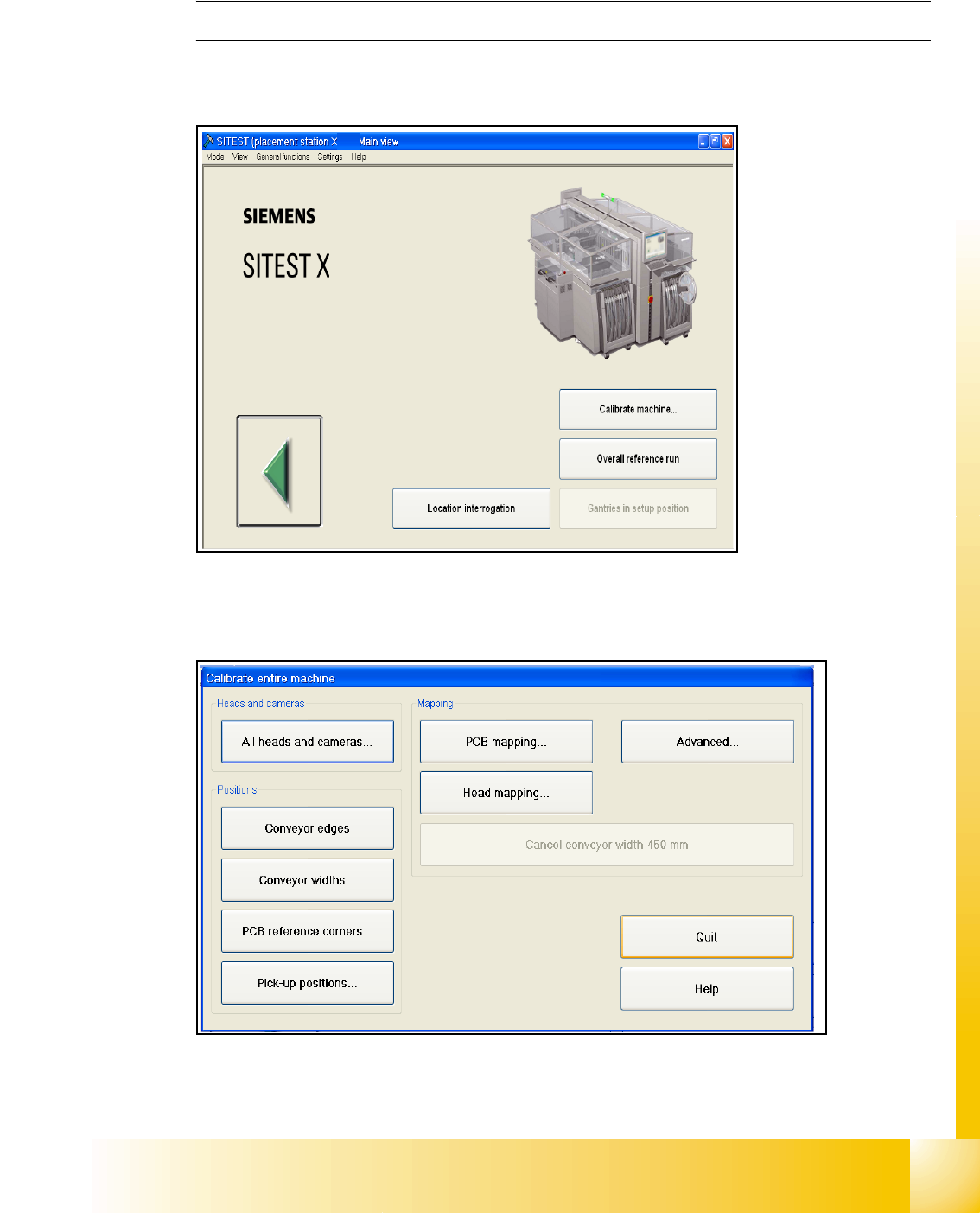
– Start Sitest
Fig. 11.2 - 3 Calibrating the entire machine
– Choose "Calibrate machine..."
Fig. 11.2 - 4 Main menu for calibrating the entire machine
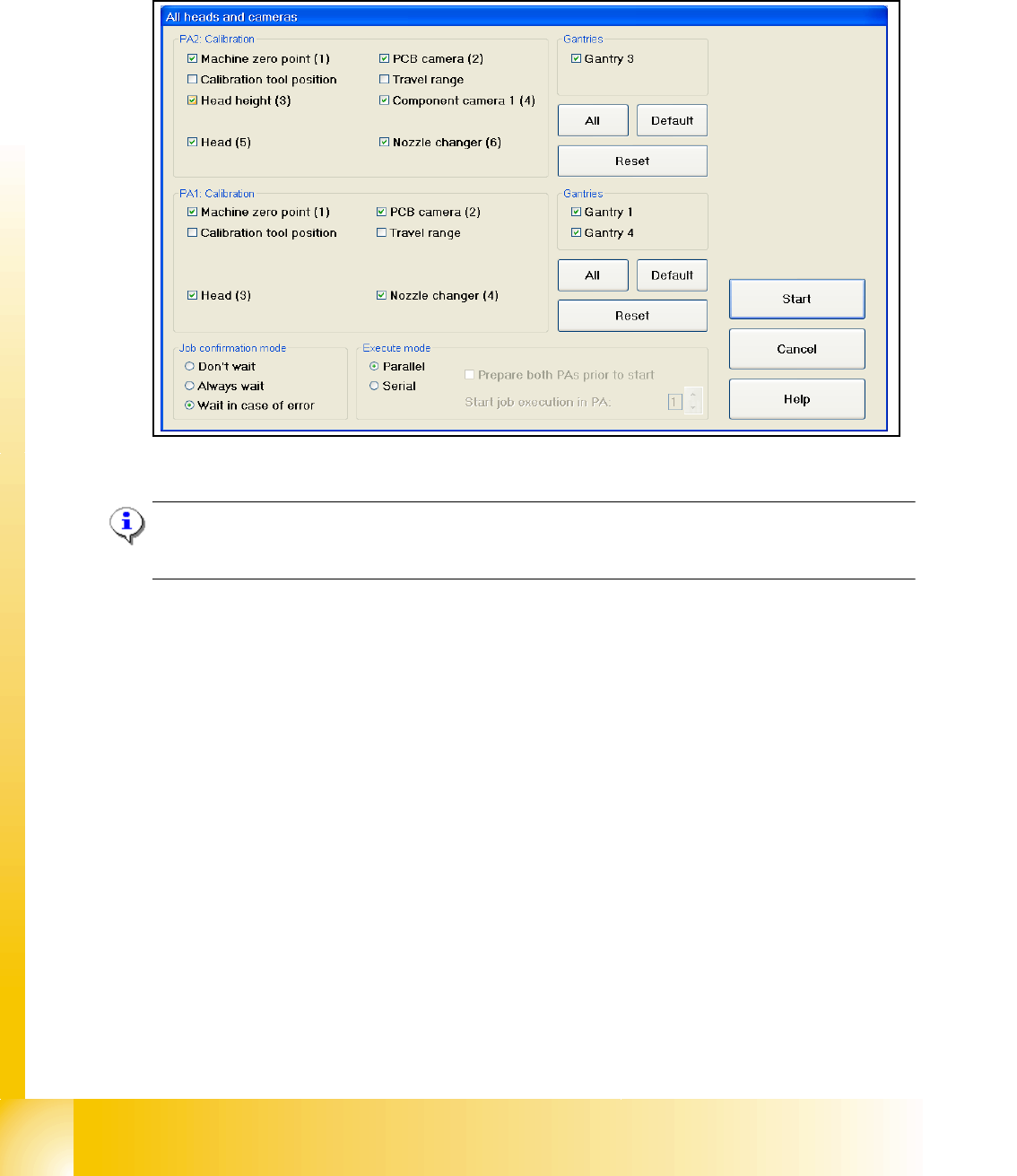
– Choose "All heads and cameras..."
1 - 18
Student Guide SIPLACE X
11 Sitest Edition 09/2005
18
11.2.6 ALL heads and cameras
Depends of the configuration the X - machine about the heads on Gantry 1 and Gantry 2 the cal-
ibration seqeuence is different.
Fig. 11.2 - 5 All heads and cameras (default settings)
Note:
If you want to calibrate only one placement area deactivate all points in the field PAx Calibration
and Gantries.
The Calibration steps for the C&P head and Twin head see Fig. 11.2 - 6. and Fig. 11.2 - 7.
➠ Select all points which you must calibrate
➠ Select the execute mode parallel or serial ( For the parallel mode prepare both placement ar-
eas, calibration tool and nozzles)
➠ Select the job confirmation mode
➠ Press the START button
Job confirmation mode 11
Don't wait: When this function is activated, the next job is carried out immediately after a job is
completed or an error occurs, without waiting for confirmation.
Always wait: When this function is activated, the next job is not carried out until confirmation is
received after a job is completed or an error occurs. You must click the Next job button to do this.
Wait in case of error: When this function is activated, the job is interrupted if an error occurs and
the next job is not carried out until confirmation is received. You must click the Next job button to
do this.
1 - 19
Student Guide SIPLACE X
Edition 09/2005 11 Sitest
19
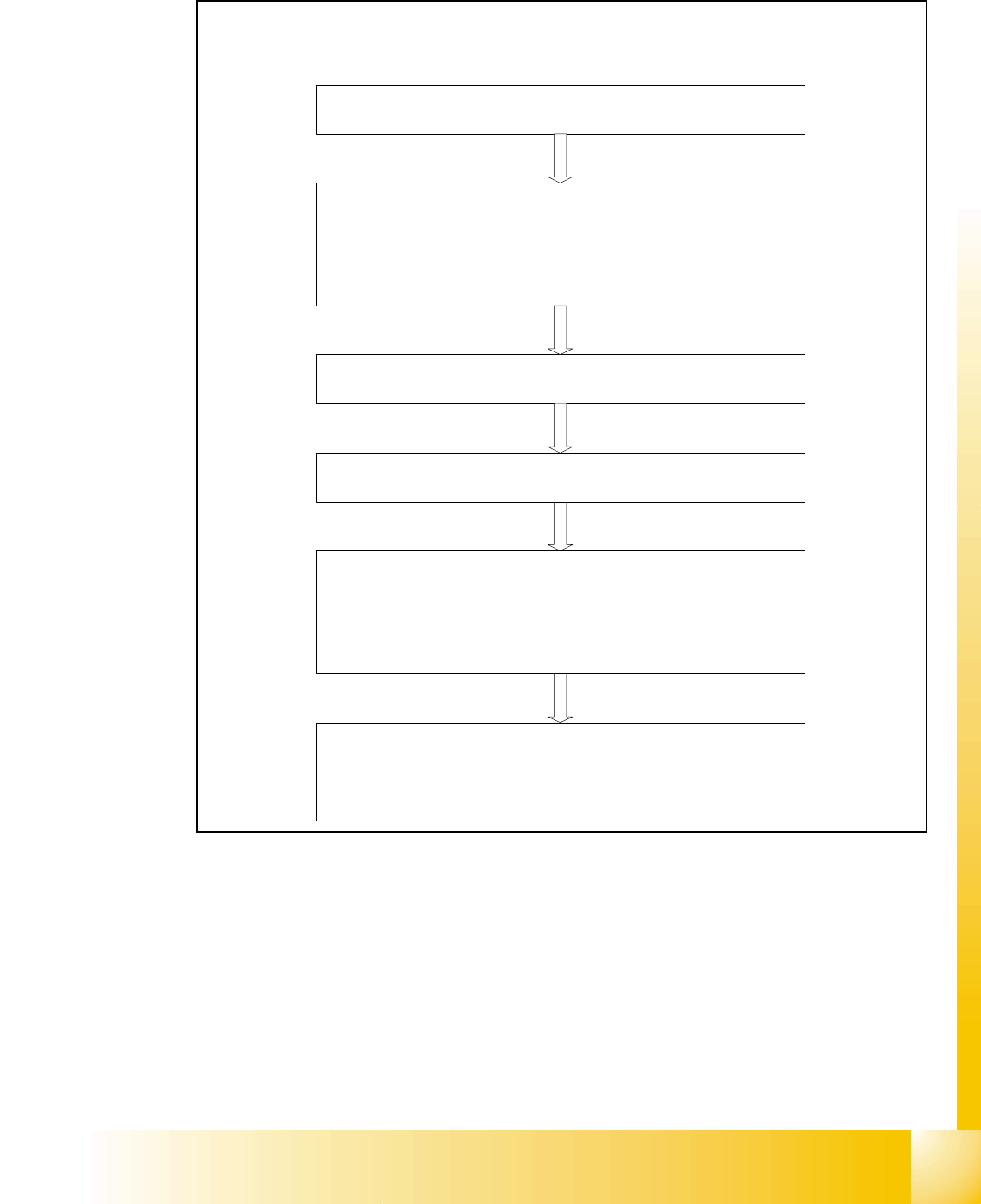
11.2.6.1 C&P head
Fig. 11.2 - 6 Sequence C&P head calibration
Sequence of calibrate the C&P head
Machine zero point
Calibration tool position
PCB camera
y Camera coefficient (image scale -nm/pixel)
y Calibrate the camera center
y Calibrate camera angle to the MA-coordinate system
Travel range X/Y Axis
y calibrate the max and min position of the travel range
C&P head
y Camera coefficient (image scale -nm/pixel), Angle
y Head offset (Offset PCB camera to component camera)
y Segmentoffset II (bottom)
y Segmentoffset I (top)
C&P head nozzle changer
y Calibrate the pick up position all magazines
y Calibrate pick up height
y Calibrate reject position