SiplaceX4_en.pdf - 第525页
1 - 20 S tudent Guide SIPLACE X 1 1 Sitest Edition 09/2005 20 1 1.2.6.2 T win head Fig. 1 1.2 - 7 Sequence T win head calibration Sequence of c alibrate the Twin head Machine ze ro poi nt Cali bration tool positi on PCB …

1 - 19
Student Guide SIPLACE X
Edition 09/2005 11 Sitest
19
11.2.6.1 C&P head
Fig. 11.2 - 6 Sequence C&P head calibration
Sequence of calibrate the C&P head
Machine zero point
Calibration tool position
PCB camera
y Camera coefficient (image scale -nm/pixel)
y Calibrate the camera center
y Calibrate camera angle to the MA-coordinate system
Travel range X/Y Axis
y calibrate the max and min position of the travel range
C&P head
y Camera coefficient (image scale -nm/pixel), Angle
y Head offset (Offset PCB camera to component camera)
y Segmentoffset II (bottom)
y Segmentoffset I (top)
C&P head nozzle changer
y Calibrate the pick up position all magazines
y Calibrate pick up height
y Calibrate reject position
1 - 20
Student Guide SIPLACE X
11 Sitest Edition 09/2005
20
11.2.6.2 Twin head
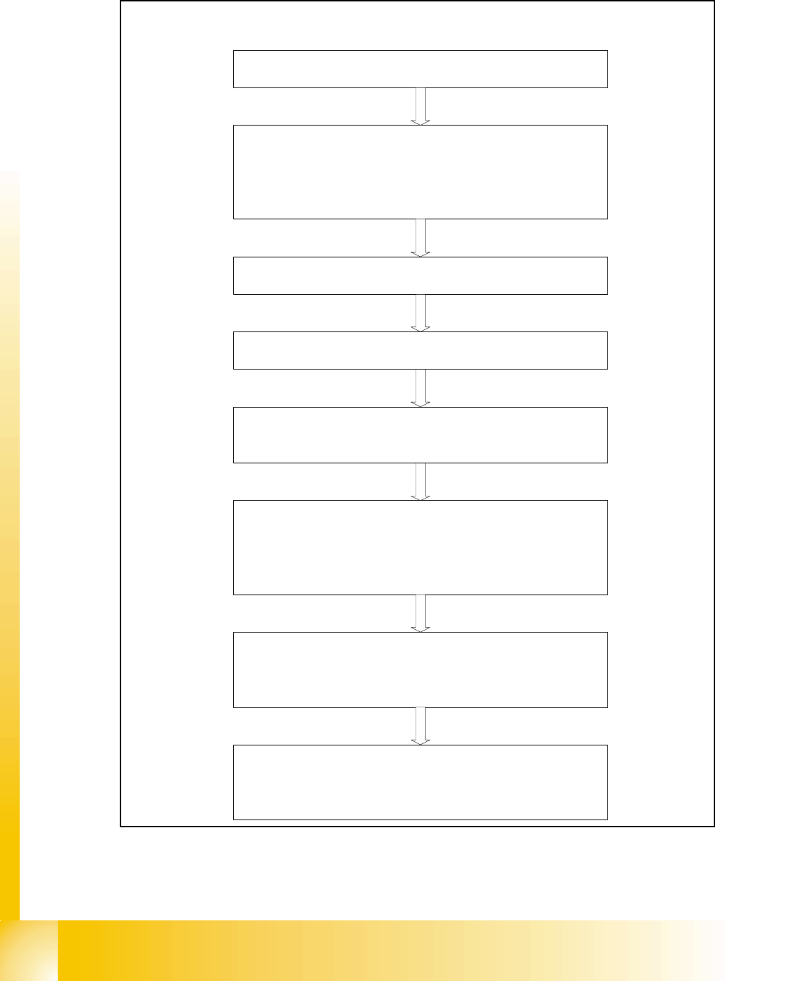
Fig. 11.2 - 7 Sequence Twin head calibration
Sequence of calibrate the Twin head
Machine zero point
Calibration tool position
PCB camera
y Camera coefficient (image scale -nm/pixel)
y Calibrate the camera center
y Calibrate camera angle to the MA-coordinate system
Travel range X/Y Axis
y calibrate the max and min position of the travel range
Twin head height
y Calibrate the height of the segment 1 and 2 (reference is
the top of the conveyor rail)
Twin head IC-camera
y Focus level
y Camera coefficient (image scale -nm/pixel), Angle
y IC camera position
y IC camera position fiducial
Twin head nozzle changer
y Calibrate the pick up position all magazines
y Calibrate pick up height
y Calibrate reject position
Twin head
y Head offset Segment 1 (PCB camera to Segment 1)
y Head offset Segment 2 (PCB camera to Segment 2)
1 - 21
Student Guide SIPLACE X
Edition 09/2005 11 Sitest
21
11.2.7 Calibrate the conveyor edges
– Choose "conveyor edges"
fThis function will be directly done, there are no further adjustments necessary.
Description for calibrating the conveyor edges see chapter 11.2.14.1
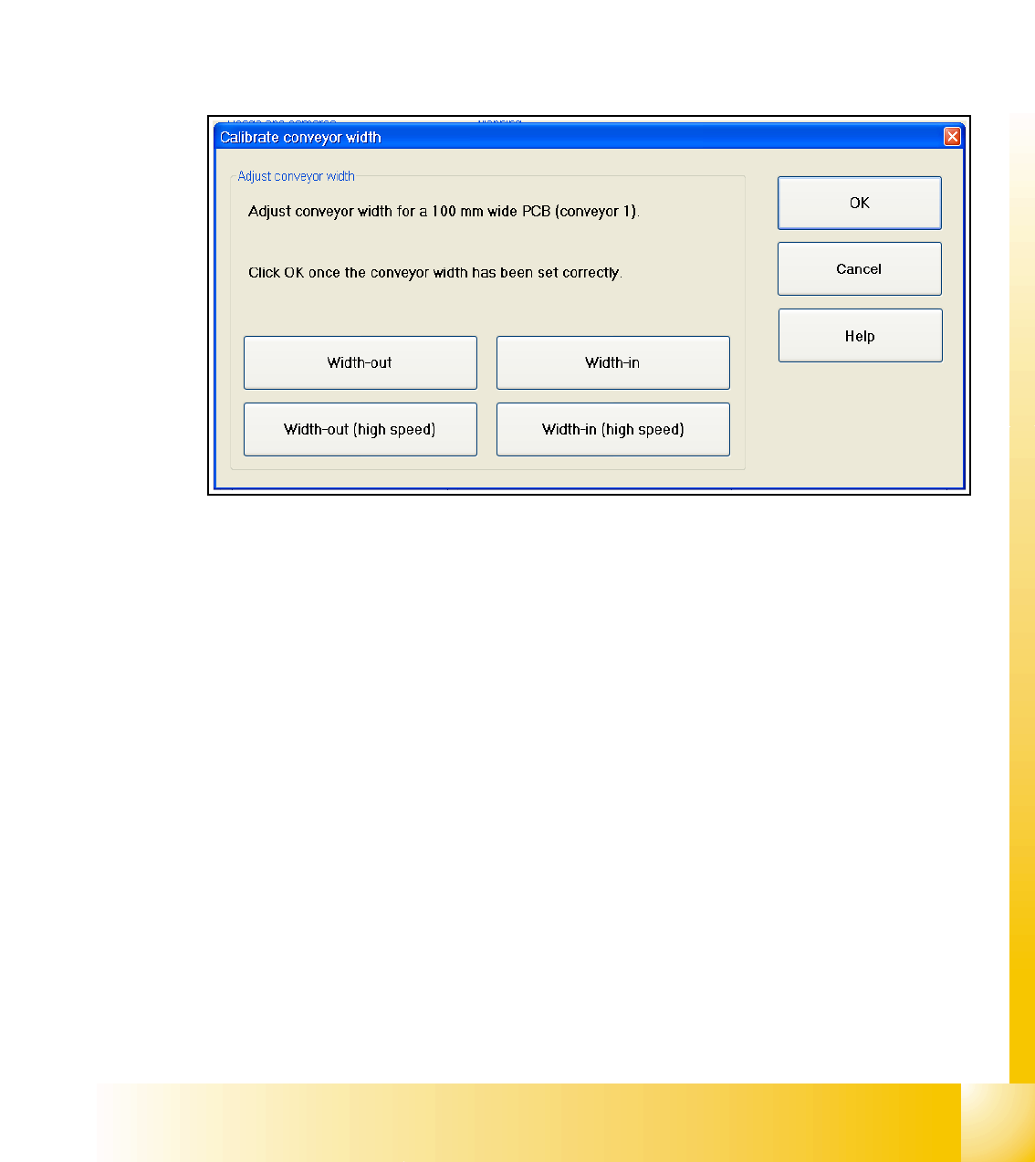
11.2.8 Calibrate the conveyor widths
– Choose "conveyor width..."
Fig. 11.2 - 8 Sub menu calibrate the conveyor width
Description for calibrating the conveyor width see chapter 11.2.14.2